Output device

a technology of output device and output, which is applied in the direction of electric variable regulation, process and machine control, instruments, etc., can solve the problems of low gain of amplifier, easy response, and worse response of output, so as to improve the transient response characteristic of output and reduce current consumption

Active Publication Date: 2010-12-23
MITSUMI ELECTRIC CO LTD
View PDF8 Cites 12 Cited by
  • Summary
  • Abstract
  • Description
  • Claims
  • Application Information

AI Technical Summary

Benefits of technology

[0013]In one aspect of the invention, the present disclosure provides an output device which can improve the transient response characteristic of the output and can reduce the current consumption.

Problems solved by technology

A regulator IC has a problem in that the response of the output gets worse when the load current is changed abruptly.
For example, in a case of a low power regulator IC, the gain of the amplifier is low and the response gets worse easily.
If the response worsens, there may be a possibility that the actual output voltage of the regulator IC is lower than the required output voltage.
Therefore, the current consumption of the whole constant voltage circuit will be increased due to the current consumption of the additional reference voltage generating circuit.

Method used


Image

  • Output device
  • Output device
  • Output device

Examples


first embodiment

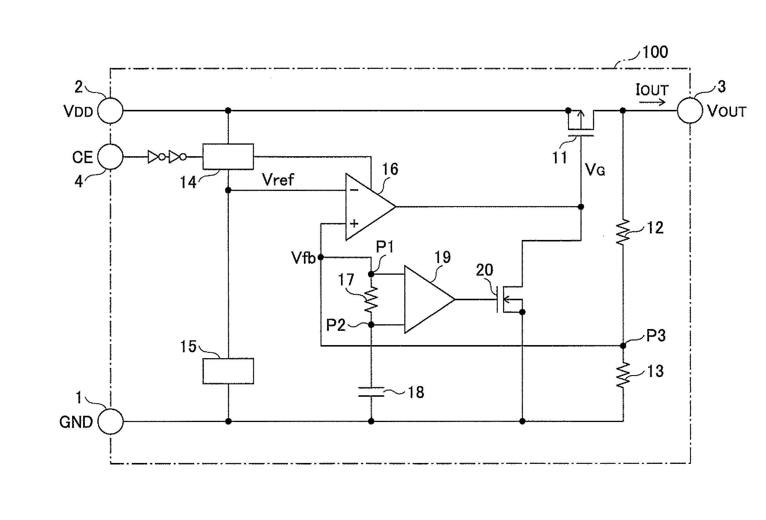
[0022]FIG. 3 is a circuit diagram illustrating the composition of a regulator IC 100 of the invention.

[0023]As illustrated in FIG. 3, the regulator IC 100 includes a ground terminal 1, a power input terminal 2, an output voltage terminal 3, and a control terminal 4 which are provided as external terminals for connecting the regulator IC 100 to external devices.

[0024]The ground terminal 1 is connected to the ground (GND) which is substantially equal to 0 (zero) V. The power input terminal 2 is connected to a power supply line, and an input voltage VDD (for example, 5V) from the power supply line is input to the power input terminal 2. The output voltage terminal 3 is connected to an output line for supplying an output current Iout to a load, and an output voltage Vout from the output voltage terminal 3 is output to the output line. A control signal for switching ON / OFF of the outputting of the output voltage Vout to the output line is input to the control terminal 4.

[0025]As illustra...

second embodiment

[0036]Next, FIG. 4 is a circuit diagram illustrating the composition of a regulator IC 200 of the invention. In FIG. 4, the elements which are the same as corresponding elements in FIG. 3 are designated by the same reference numerals and a description thereof will be omitted.

[0037]As illustrated in FIG. 4, the regulator IC 200 is an output device which includes: an output transistor 11 which outputs the output current Iout; a first driver which drives the output transistor 11 so that a feedback voltage Vfb of the output voltage Vout of the output transistor 11 is in agreement with a reference voltage Vref; an RC circuit which has a capacitor 18 connected to the ground and a resistor 17 connected in series to the capacitor 18; and a second driver which has an adjusting part that adjusts the output current Iout by driving the output transistor 11 based on the voltage between the ends of the resistor 17. The first driver includes a first voltage amplifier 16 and a first adjusting trans...


PUM


Abstract

An output device includes an output transistor that outputs an output current, a first driver that drives the output transistor so that a feedback voltage of an output voltage of the output transistor is in agreement with a reference voltage, an RC circuit that has a capacitor connected to the ground and a resistor connected in series to the capacitor, and a second driver that drives the output transistor to increase the output current when a potential difference between ends of the resistor, generated by the feedback voltage supplied between ends of the RC circuit, is increased by a decrease of the output voltage.

Description

CROSS-REFERENCE TO RELATED APPLICATION[0001]This application is based upon and claims the benefit of priority of Japanese patent application No. 2009-146207, filed on Jun. 19, 2009, the entire contents of which are incorporated herein by reference in their entirety.BACKGROUND OF THE INVENTION[0002]1. Field of the Invention[0003]This invention relates to an output device which supplies a current to a load.[0004]2. Description of the Related Art[0005]A regulator IC has a problem in that the response of the output gets worse when the load current is changed abruptly. In this context, the term “worse” means that the response becomes nonlinear. For example, in a case of a low power regulator IC, the gain of the amplifier is low and the response gets worse easily. If the response worsens, there may be a possibility that the actual output voltage of the regulator IC is lower than the required output voltage.[0006]For example, FIG. 1 illustrates the composition of a regulator IC according t...

Claims


Application Information

Patent Timeline
Patent Type & Authority Applications(United States)
IPC IPC(8): G05F1/10
CPCG05F1/575
Inventor TERADA, AKIHIROTAKANO, YOICHIMAKI, SHINICHIRO
Owner MITSUMI ELECTRIC CO LTD
Why Eureka
Try Eureka