High-Resolution NMR Probe

a high-resolution, probe technology, applied in the direction of reradiation, measurement using nmr, instruments, etc., can solve the problems of high energy release and absorbed, complex cooling structure, high cost of fabrication, etc., and achieve the effect of simple structure and economical fabrication

Active Publication Date: 2010-12-23
JEOL RESONANCE
View PDF4 Cites 28 Cited by
  • Summary
  • Abstract
  • Description
  • Claims
  • Application Information

AI Technical Summary

Benefits of technology

[0012]In view of the foregoing, it is an object of the present invention to provide

Problems solved by technology

Generally, NMR spectroscopy has the problem that the amounts of energies released and absorbed are much smaller than in visible light spectroscopy, UV spectroscopy, and IR spectroscopy because

Method used


Image

  • High-Resolution NMR Probe
  • High-Resolution NMR Probe
  • High-Resolution NMR Probe

Examples


embodiment 1

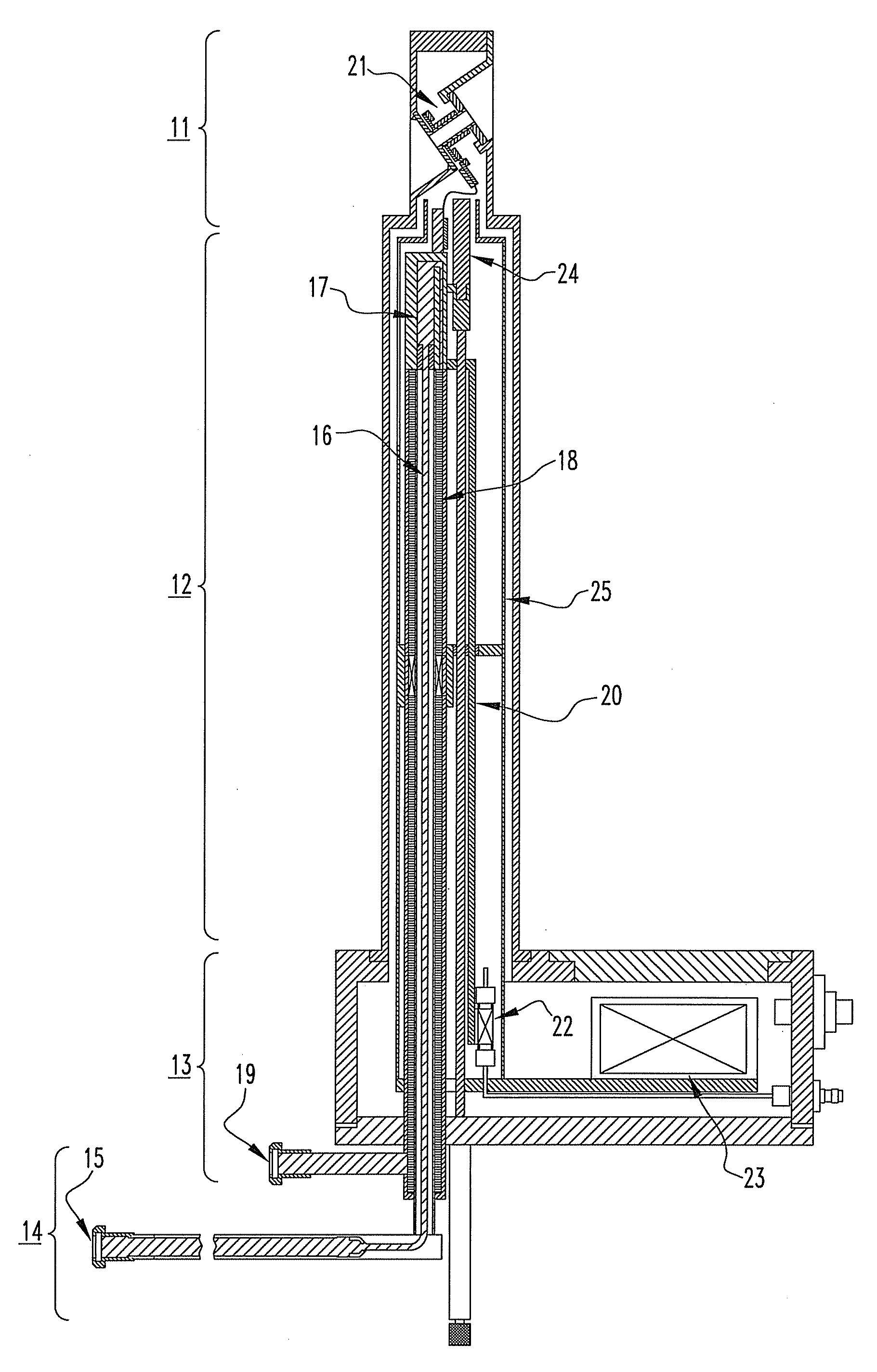
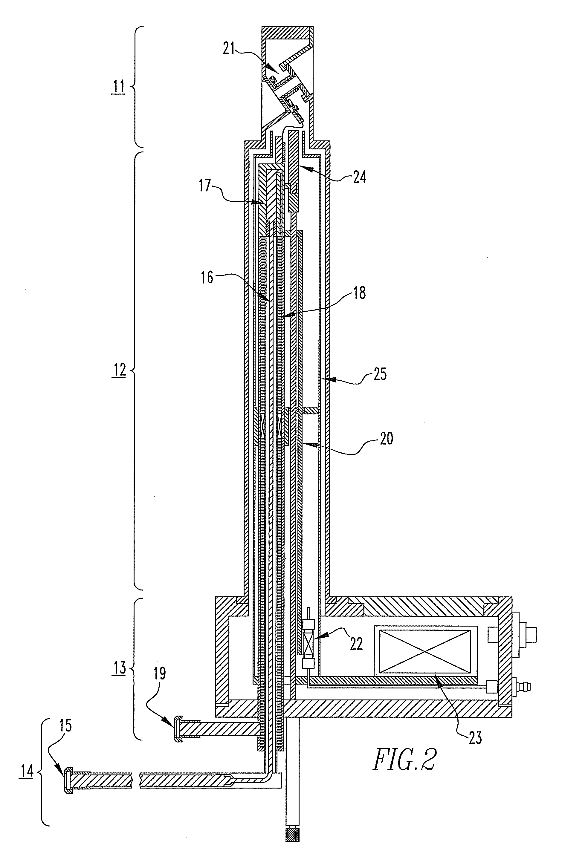
[0036]FIG. 2 shows one embodiment of the invention in which the invention is applied to a high-resolution NMR probe adapted for investigation of solid samples. The probe is composed of four major components: detection portion 11, relay portion 12, electrical circuitry 13, and refrigerant inlet-outlet portion 14.

[0037]The detection portion 11 applies an RF magnetic field to a sample while rotating a sample tube at high speed, the tube being used for NMR measurements on solids. The detection portion 11 has a transmit-receive coil 21 for detecting an NMR signal emanating from the sample after it is irradiated with the RF magnetic field.

[0038]The relay portion 12 places the detection portion 11 in position within a bore (vertical hole) formed in a superconducting magnet (not shown). The relay portion 12 is elongated to permit the detection portion 11 to be placed within the strong static magnetic field produced by the superconducting magnet.

[0039]The electrical circuitry 13 incorporates...

embodiment 2

[0069]FIG. 9 shows another embodiment of the present invention, in which the invention is applied to a solid-sample, high-resolution NMR probe. FIG. 9 is an enlarged view of various portions starting from electrical circuitry 13 and ending with refrigerant inlet portion 14. These portions are located at the exit of the bore (vertical hole) in a superconducting magnet and so are spread laterally, in the same way as in Embodiment 1 described previously in connection with FIGS. 2-7.

[0070]In Embodiment 1, the preamplifier 22 is thermally connected to the 4 K stage bar 20 to cool down the preamplifier 22 close to 5 to 10 K. In the present embodiment, however, the preamplifier 22 is held at the same position as the diode box 53. That is, the preamplifier is screwed to a portion of a copper or aluminum plate forming an extension of the 50 K radiation shield 45. The preamplifier is cooled close to the same temperature as the diode box 53, i.e., about 50 K, more preferably below 50 K. We hav...


PUM


Abstract

A high-resolution NMR probe is offered which is simple in structure and can be fabricated at low cost. The inside of the probe is maintained in a vacuum to adiabatically isolate the inside from the outside. Liquid helium is sent into a first heat exchanger located immediately close to a measurement portion via the innermost region of a triple tube placed in the vacuum. The helium is evaporated in the exchanger to cool a transmit-receive coil and a variable capacitor. The evaporated helium gas is returned via the outermost region of the triple tube. At this time, a radiation shield placed in the vacuum is cooled by a second heat exchanger placed in the return path.

Description

BACKGROUND OF THE INVENTION[0001]1. Field of the Invention[0002]The present invention relates to a high-resolution NMR probe and, more particularly, to a high-resolution NMR probe capable of measuring solid samples at higher sensitivity than heretofore.[0003]2. Description of Related Art[0004]An NMR spectrometer is an instrument for analyzing the molecular structure of a sample under investigation by placing the sample in a static magnetic field, irradiating the sample with an RF signal, detecting a feeble RF signal (NMR signal) emanating from the sample, and extracting information about the molecular structure contained in the detected signal.[0005]FIG. 1 schematically shows the structure of an NMR spectrometer. This instrument has an RF oscillator 1 producing an RF signal, which is controlled in terms of phase and amplitude by a phase controller 2 and an amplitude controller 3 and sent to a power amplifier 4.[0006]The power amplifier 4 amplifies the RF signal to a level necessary ...

Claims


Application Information

Patent Timeline
IPC IPC(8): G01R33/44G01R1/06
CPCG01R1/067G01R33/3403G01R33/307
Inventor TAKEGOSHI, KIYONORIMIZUNO, TAKASHI
Owner JEOL RESONANCE
Why Eureka
Try Eureka