
High efficiency transmitter for wireless communication

a high-efficiency, wireless communication technology, applied in the field of wireless communication systems, can solve the problems of insufficient efficiencies, poor power consumption and power conversion of wireless communication transmitters, and insufficient efficiency of linear amplifiers used in wireless communication networks in the early 90's

Active Publication Date: 2010-12-23
ALCATEL LUCENT SAS
View PDF6 Cites 63 Cited by
  • Summary
  • Abstract
  • Description
  • Claims
  • Application Information

AI Technical Summary

Benefits of technology

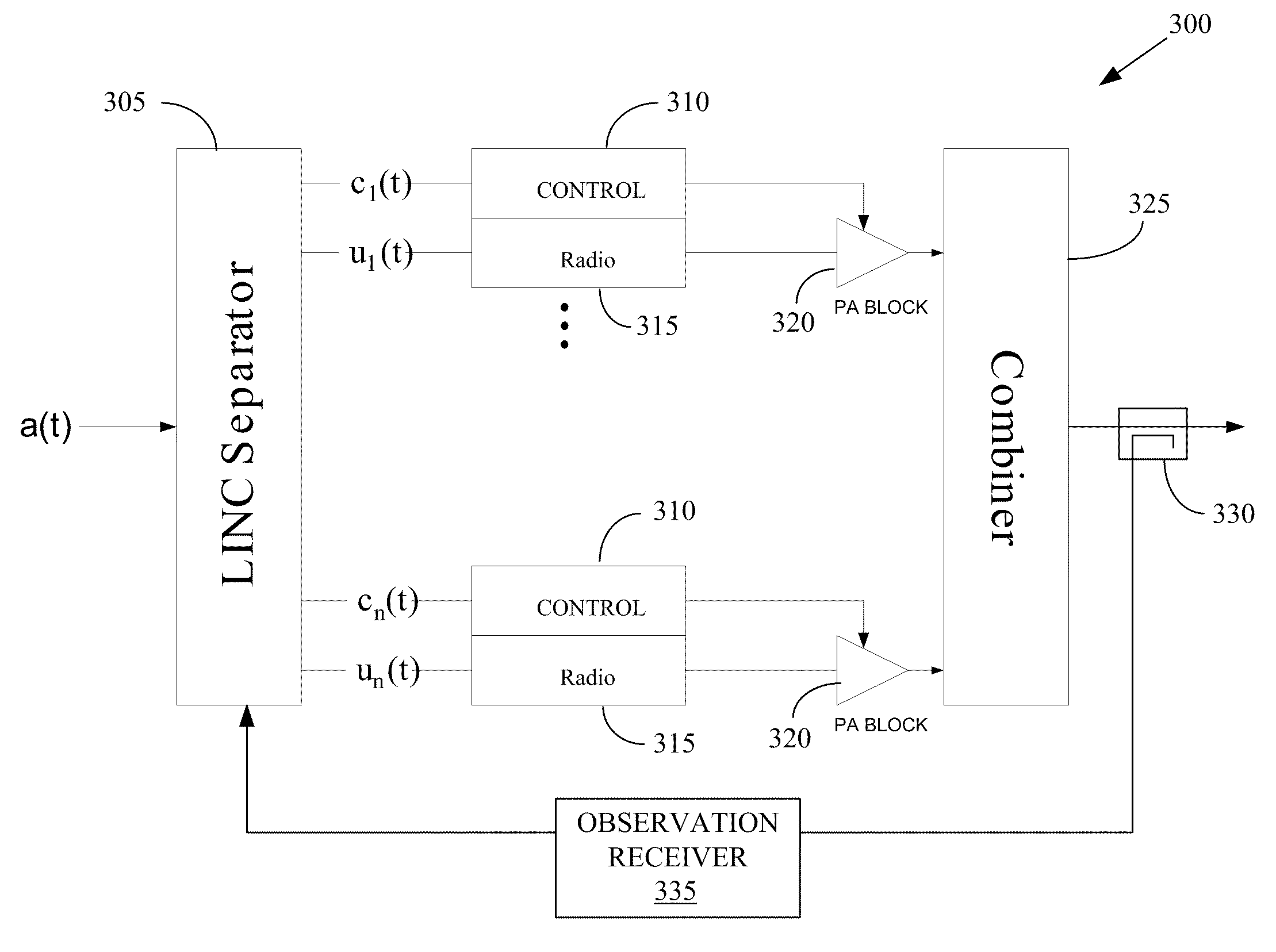
[0009]In one embodiment, a LINC amplifier is provided. The amplifier may include a signal separator for decomposing an input signal into constant envelope signals and amplifier circuits for amplifying the constant envelope signals. The amplifier may also include a combiner for combining the amplified constant envelope signals to form an output signal that is an amplified representation of the input signal. Linear correction circuits can be used to apply gain, phase, and / or delay correction to the constant envelope signals. The corrections are determined based upon a feedback portion of the output signal. Pre-distortion circuits can be used to apply a non-linear pre-distortion to the constant envelope signals. The non-linear pre-distortion is determined based upon the feedback portion of the output signal.

Problems solved by technology

Power consumption and power conversion by wireless communication transmitters have historically been poor.
Linear amplifiers used in wireless communication networks were only a few percent efficient in the early 90's.
However, even these efficiencies are now thought to be insufficient.
Although the theoretical foundations for the required signal processing are sound, real-world implementation of the mathematics of Chireix signal processing proved difficult and analog LINC amplifiers have to date failed to achieve the theoretical efficiencies.
However, attempts to construct commercial implementations of a LINC amplifier for a wireless transmitter have also failed to achieve the theoretical maximum efficiencies.
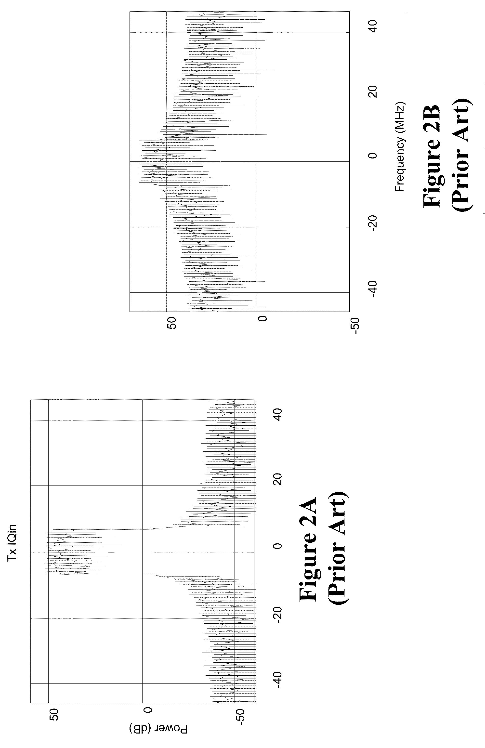
The failure of both the analog and digital approaches to achieve the theoretical efficiencies results, at least in part, from numerous path impairments in LINC systems.
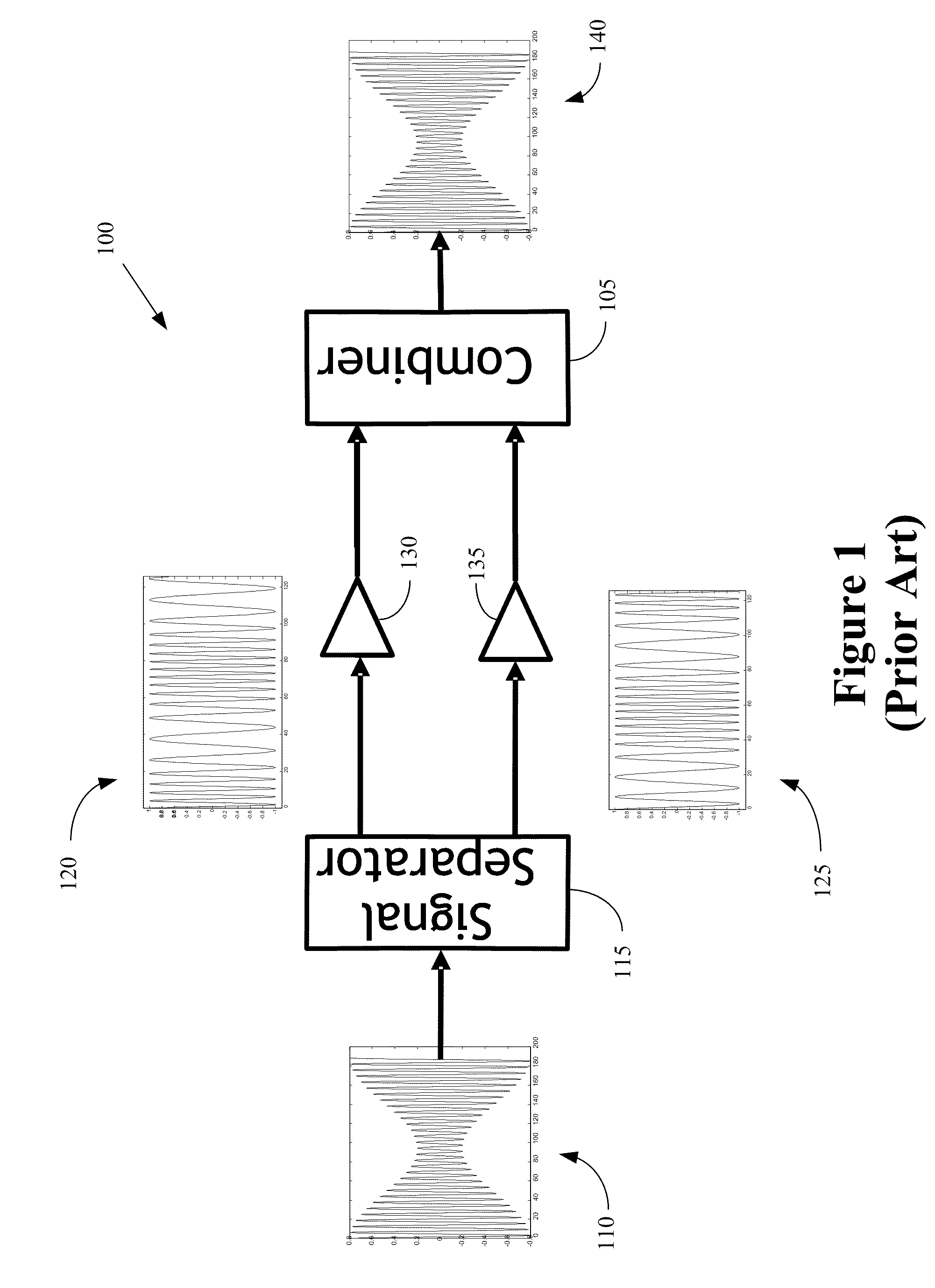
However, in practice each element in the LINC amplifier 100 introduces slightly different gains, delays, and / or phase shifts, which can significantly degrade the quality of the amplified signal 140.
Thus, the relatively small gain imbalance of 0.1 dB significantly degrades the quality of the reconstructed amplified signal.

Method used


Image

  • High efficiency transmitter for wireless communication
  • High efficiency transmitter for wireless communication
  • High efficiency transmitter for wireless communication

Examples


Embodiment Construction

[0020]Illustrative embodiments are described below. In the interest of clarity, not all features of an actual implementation are described in this specification. It will of course be appreciated that in the development of any such actual embodiment, numerous implementation-specific decisions may be made to achieve the developers' specific goals, such as compliance with system-related and business-related constraints, which may vary from one implementation to another. Moreover, it will be appreciated that such a development effort might be complex and time-consuming, but would nevertheless be a routine undertaking for those of ordinary skill in the art having the benefit of this disclosure.

[0021]The disclosed subject matter will now be described with reference to the attached figures. Various structures, systems and devices are schematically depicted in the drawings for purposes of explanation only and so as to not obscure the present invention with details that are well known to tho...


PUM


Abstract

The present invention provides an amplifier for a wireless transmitter. In one embodiment, the amplifier includes a signal separator for decomposing an input signal into constant envelope signals and amplifier circuits for amplifying the constant envelope signals. The amplifier also includes a combiner for combining the amplified constant envelope signals to form an output signal that is an amplified representation of the input signal. Linear correction circuits are used to apply gain, phase, and / or delay correction to the constant envelope signals. The corrections are determined based upon a feedback portion of the output signal. Pre-distortion circuits are used to apply a non-linear pre-distortion to the constant envelope signals. The non-linear pre-distortion is determined based upon the feedback portion of the output signal.

Description

BACKGROUND OF THE INVENTION[0001]1. Field of the Invention[0002]This invention relates generally to communication systems, and, more particularly, to wireless communication systems.[0003]2. Description of the Related Art[0004]Power consumption and power conversion by wireless communication transmitters have historically been poor. Linear amplifiers used in wireless communication networks were only a few percent efficient in the early 90's. More recently, wireless transmitters have implemented “less linear” amplifiers that use digital linearization techniques to achieve efficiencies in the 30-40% range. However, even these efficiencies are now thought to be insufficient. For example, service providers and world governments have increased pressure to decrease energy consumption and have set a target efficiency of more than 40% for future wireless transmitters. Achieving this goal would represent a revolutionary leap in efficiency for wireless transmitters, particularly in, but not lim...

Claims


Application Information

Patent Timeline
IPC IPC(8): H03F3/68
CPCH03F1/3247H03F1/0294H03F1/02H03F1/32
Inventor HONCHARENKO, WALTER
Owner ALCATEL LUCENT SAS
Learn More