
Coil component

a coil and component technology, applied in the direction of coils, transformers/inductance details, inductances, etc., can solve the problems of reducing the winding region of the wire, hard to secure the insulation and core strength, etc., to secure the insulation and strength of the ferrite core, and reserve the winding region sufficiently

Active Publication Date: 2010-12-23
TDK CORPARATION
View PDF5 Cites 15 Cited by
  • Summary
  • Abstract
  • Description
  • Claims
  • Application Information

AI Technical Summary

Benefits of technology

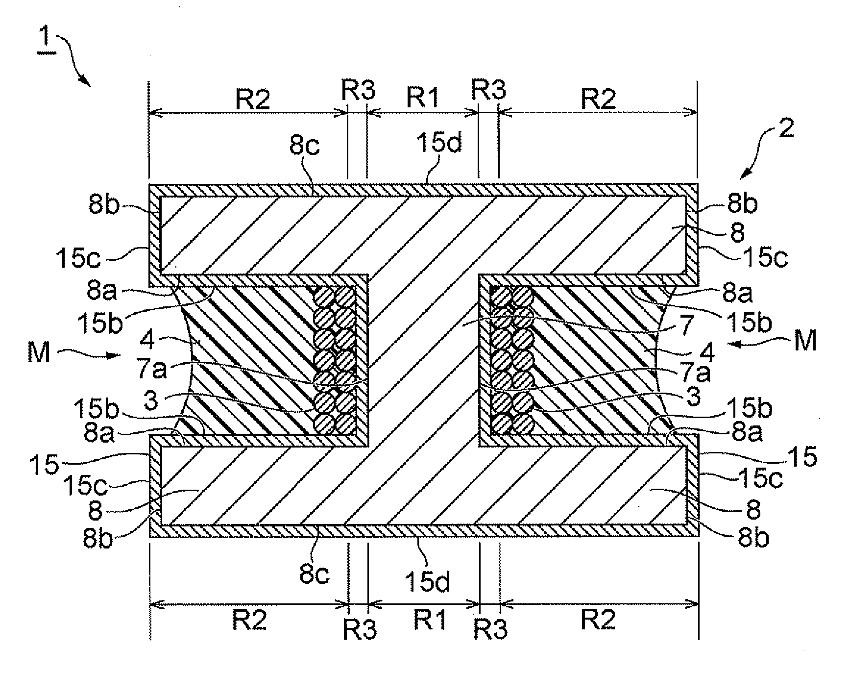
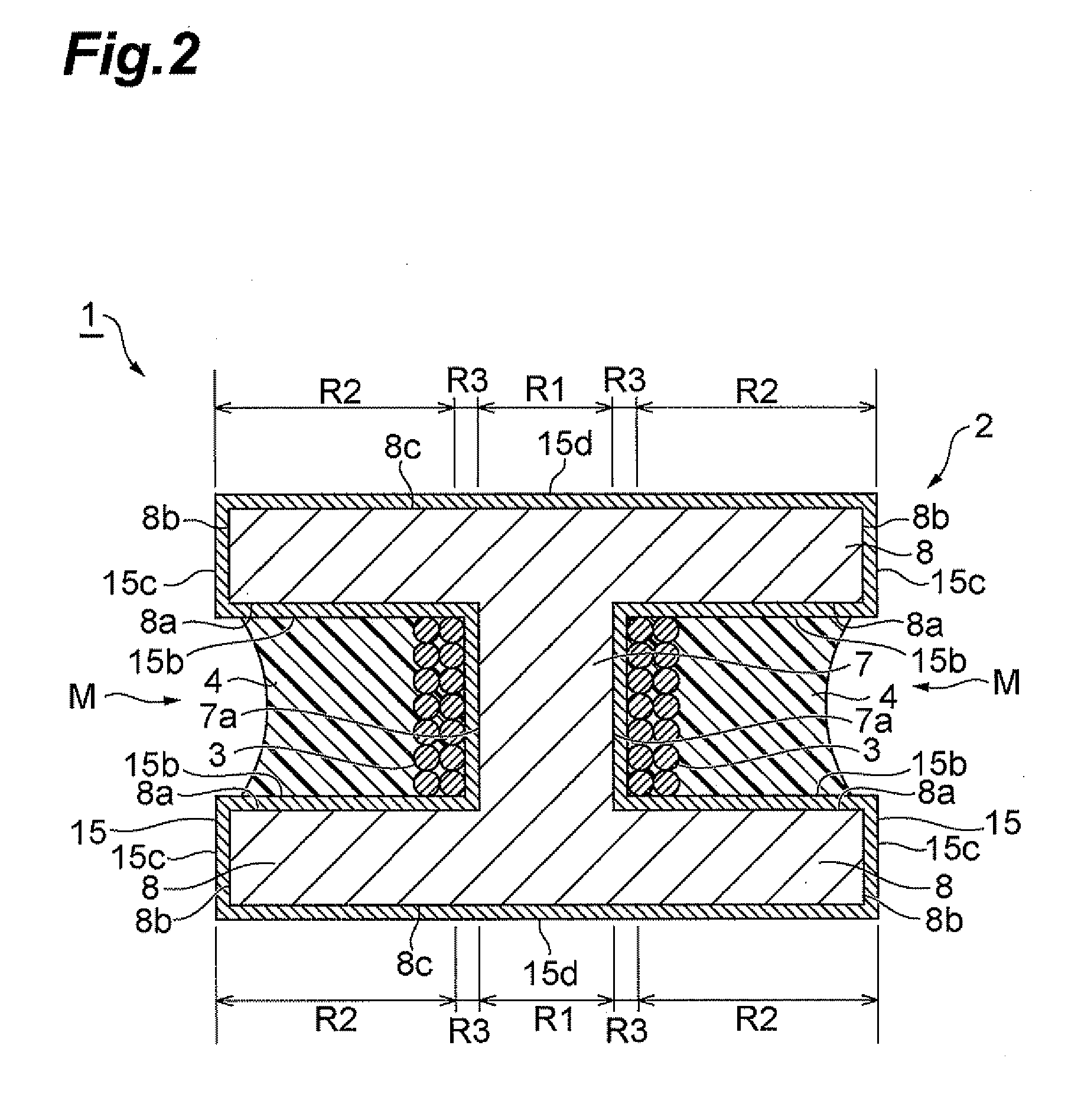
The present invention provides a coil component that can secure the insulation and strength of a ferrite core and reserve a winding region sufficiently. This is achieved by coating the surface of the Mn—Zn-based ferrite core with a glass film and adjusting the film thickness. By doing so, cracks can be inhibited from occurring in boundary parts between the winding core part and the flanges, for example. The thickness of the glass film covering the surface of the winding core part and the inner side face of the flange is smaller than the thickness of the glass film in the remaining part. This can reserve the winding region while keeping the insulation and strength. The winding core part has a higher density than the flange, but the part yielding the density difference becomes the most fragile part. The present invention can secure the insulation and strength of the ferrite core and reserve the winding region sufficiently.

Problems solved by technology

When covering the surface of a core with a glass film, however, the insulation and core strength will be hard to secure if the film thickness is insufficient, whereas a region for winding the wire (winding region) will decrease if the film thickness is too large, whereby it is necessary to adjust the film thickness.

Method used


Image

  • Coil component
  • Coil component
  • Coil component

Examples


Embodiment Construction

[0018]In the following, preferred embodiments of the coil component in accordance with the present invention will be explained in detail with reference to the drawings.

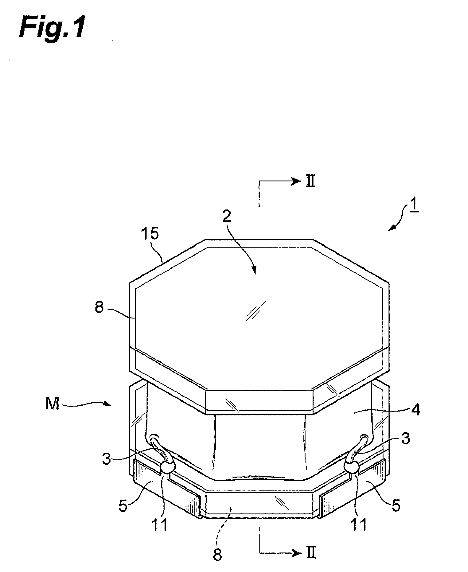
[0019]FIG. 1 is a perspective view illustrating an embodiment of the coil component in accordance with the present invention. FIG. 2 is a sectional view taken along the line II-II of FIG. 1. As illustrated in FIGS. 1 and 2, this coil component 1 comprises a drum-shaped ferrite core 2, a wire 3, a coating 4, and a pair of terminal electrodes 5, 5.

[0020]As illustrated in FIG. 2, the ferrite core 2 has a columnar winding core part 7 about which the wire 3 is wound and a pair of flanges 8, 8 which are respectively formed at both longitudinal ends of the winding core part 7. The winding core part 7 has a cross section shaped like a square whose sides are about 1 mm each, for example, and a length of about 0.3 to 1.8 mm, for example. The ferrite core 2 is shaped when a mold filled with an Mn—Zn-based ferrite powder is press...


PUM

PropertyMeasurementUnit
lengthaaaaaaaaaa
lengthaaaaaaaaaa
widthaaaaaaaaaa

Abstract

A coil component which can secure the insulation and strength of a ferrite core and reserve a winding region sufficiently is provided. By coating a surface of an Mn—Zn-based ferrite core with a glass film, this coil component can secure the insulation between the ferrite core and a terminal electrode. Coating with the glass film also ensures the strength of the ferrite core, thereby inhibiting cracks from occurring in boundary parts between a winding core part and flanges. In the coil component, at least one of the thickness of the glass film covering the surface of the winding core part and the thickness of the glass film covering the inner side face of the flange is smaller than the thickness of the glass film in the remaining part. Thus suppressing the thickness of the glass film on the surface of the winding core part and on the inner side face of the flange can sufficiently secure a winding region M.

Description

BACKGROUND OF THE INVENTION[0001]1. Field of the Invention[0002]The present invention relates to a winding type coil component.[0003]2. Related Background Art[0004]Known as a winding type coil component is one comprising a drum-shaped core having a winding core part and a pair of flanges arranged on both ends thereof and a wire wound about the winding core part. While Ni—Zn-based ferrite cores have conventionally been used for the drum-shaped core, Mn—Zn-based ferrite cores have come into use in order to secure magnetic characteristics as coil components have been reducing their sizes. The Mn—Zn-based ferrite cores incur less core loss and thus can suppress the power consumption.[0005]The Mn—Zn-based ferrite cores have characteristics better than those of the conventional Ni—Zn-based ferrite cores but are electrically conductive, which makes it necessary to apply an insulating coating to their surface when forming electrodes thereon. On a ferrite core surface in the coil component d...

Claims


Application Information

Patent Timeline
Patent Type & Authority Applications(United States)
IPC IPC(8): H01F27/29
CPCH01F17/045H01F27/324H01F27/29
Inventor KUDO, TAKASHIOHKUBO, HITOSHISHINDOH, MASATOSHI
Owner TDK CORPARATION
Learn More