Interface between an object such as a firearm and an alarm or monitoring system

US20100321186A1Inactive Publication Date: 2010-12-23CROOK D WAYNE

Image

  • Interface between an object such as a firearm and an alarm or monitoring system
  • Interface between an object such as a firearm and an alarm or monitoring system
  • Interface between an object such as a firearm and an alarm or monitoring system

Examples


Embodiment Construction

[0034]In this disclosure and the accompanying claims, terms such as “upper,”“lower,”“top,” and “bottom” may be used to describe various surfaces and other features of devices embodying the present invention. It should be appreciated that these terms are used in the context of the orientation of structures shown in the accompanying drawings.

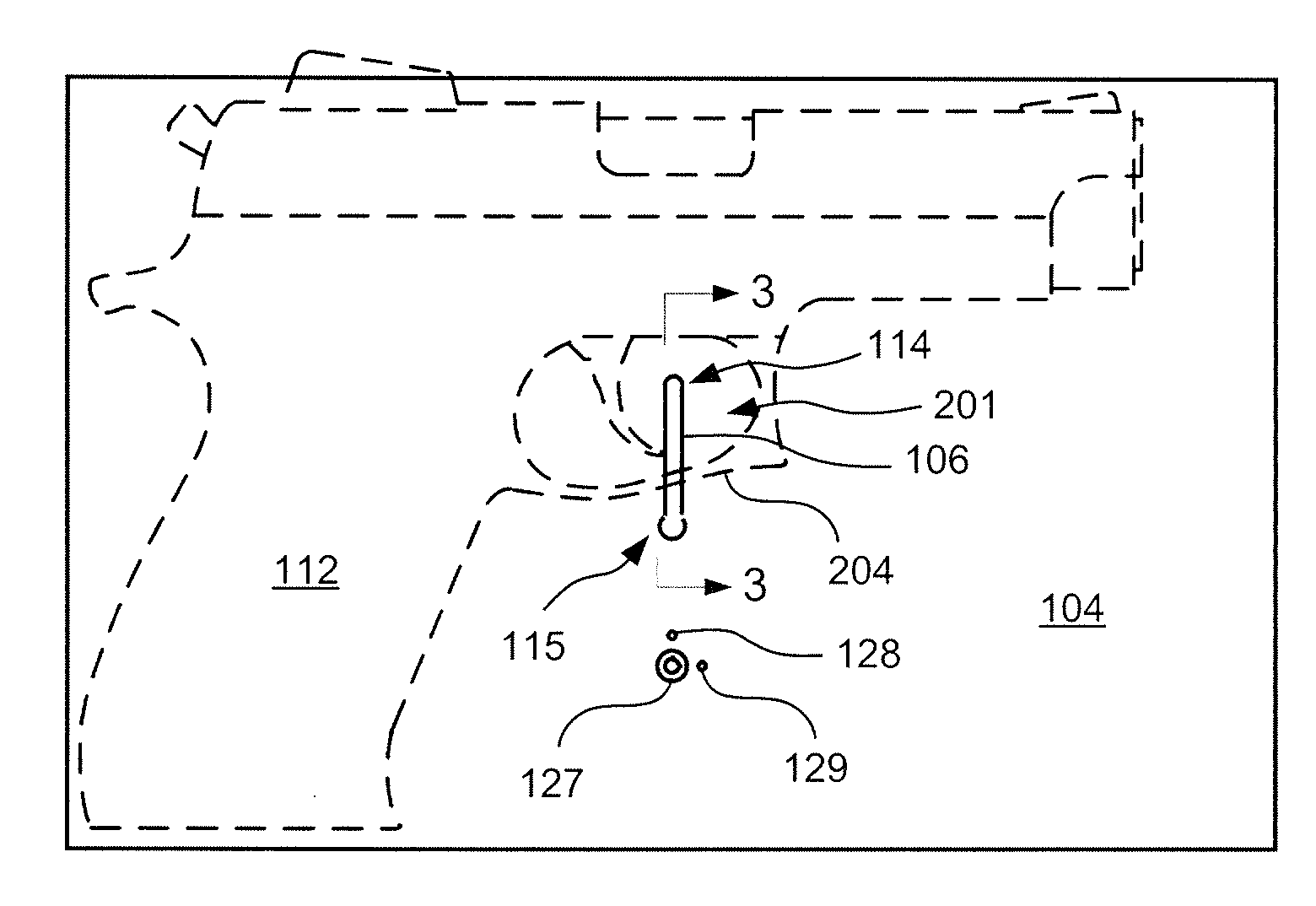
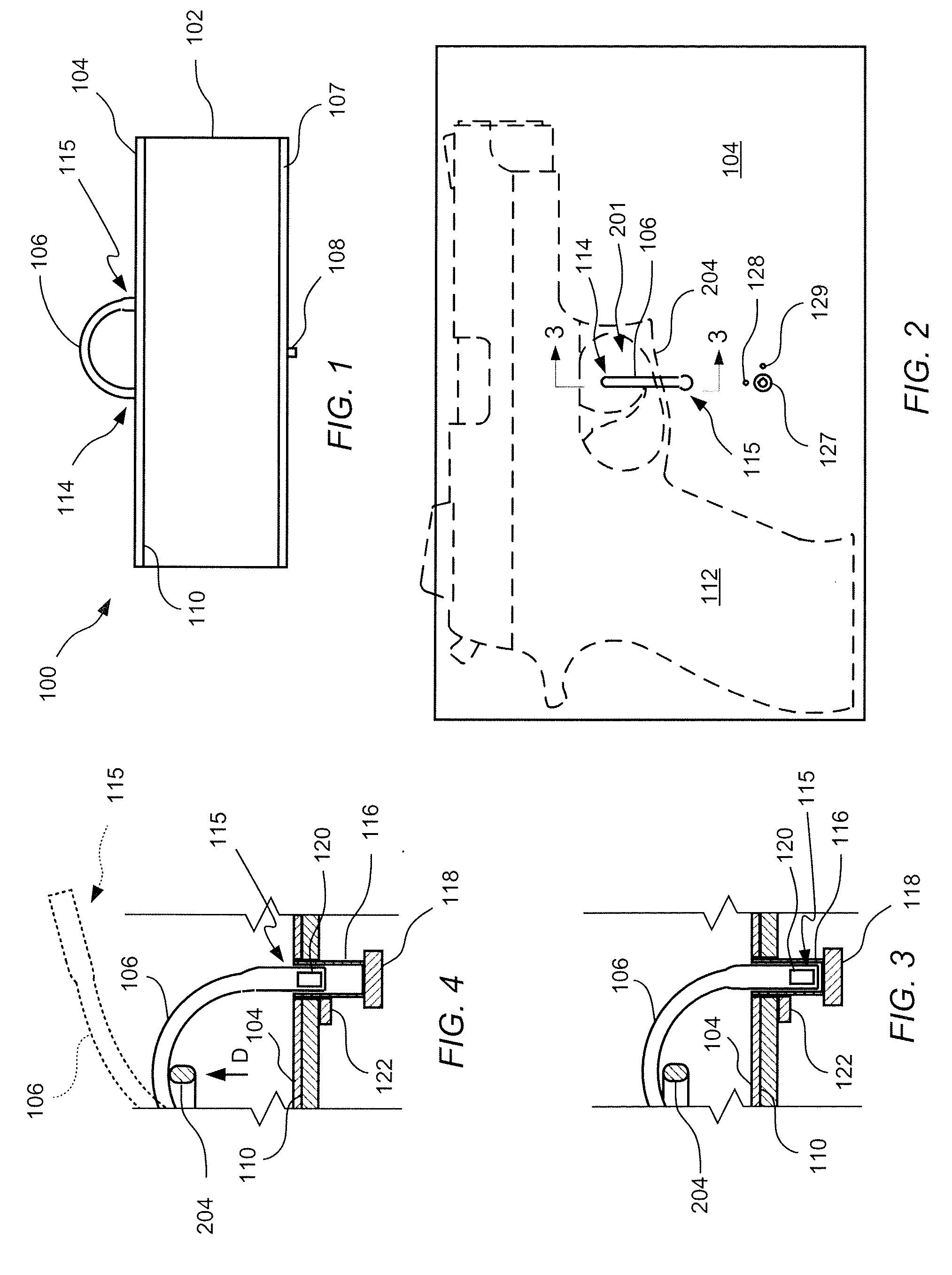
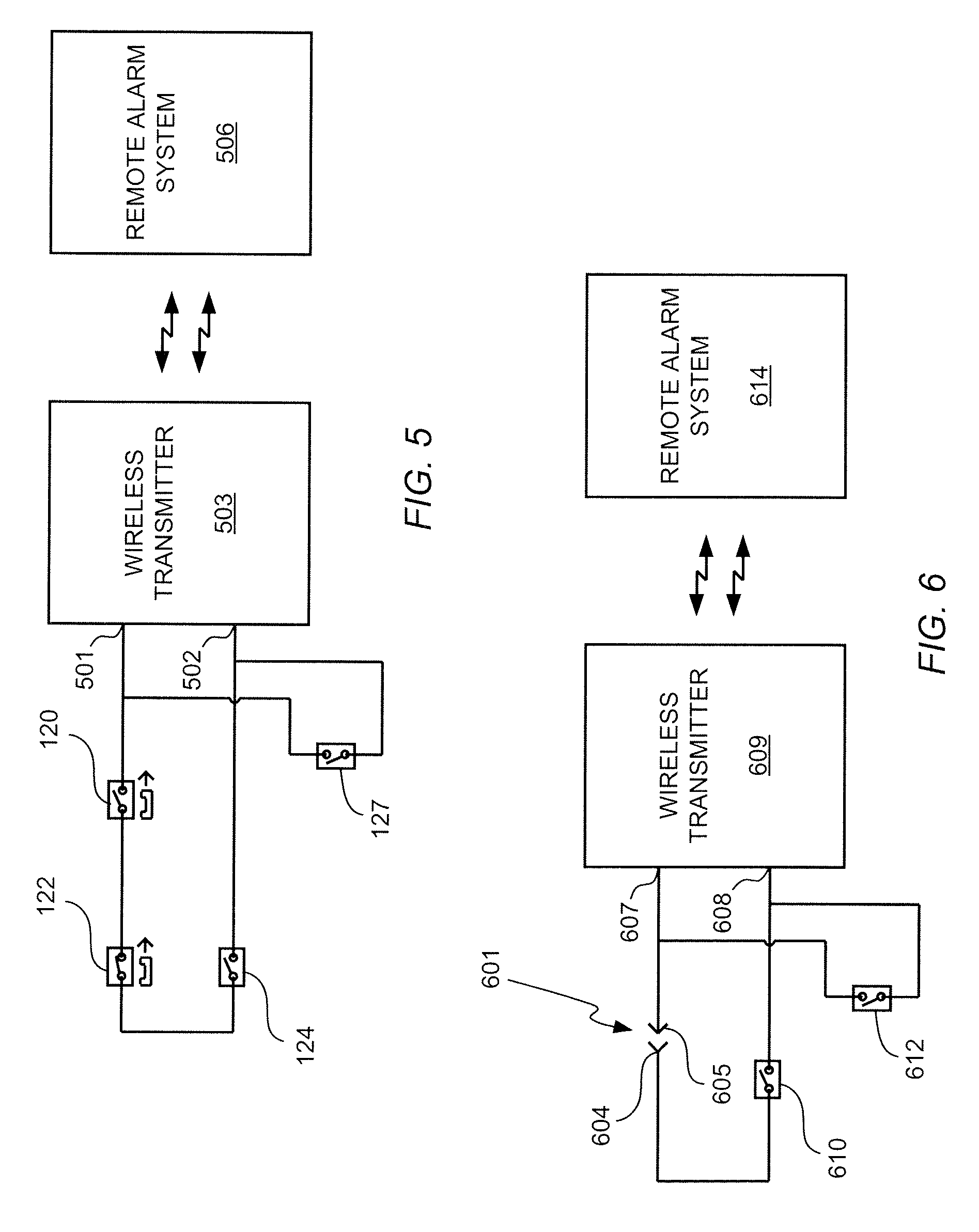
[0035]In the following description, the structure of an example strap-type interface device is described with reference to FIGS. 1-5, and certain alternate electronic components for a strap-type alarm interface device are described with reference to FIG. 6. An example probe-type alarm interface device according to the present invention is described with reference to FIGS. 7-11. A variation of the probe-type alarm interface device in which the device is integrated with a holster is described with reference to FIGS. 12-15. An additional alternate probe-type alarm interface device is described with reference to FIGS. 16-18.

[0036]Referring now to FIG....


PUM


Abstract

An interface device includes an elongated sensor strap having a secured end and an unsecured end opposite to the secured end. The unsecured end of the sensor strap represents a first sensor half, and a second sensor half is adapted to receive the first sensor half / unsecured end to form a sensor link between the two sensor halves. A deployment sensor switch provides an input to a monitoring device for an alarm system. The deployment sensor switch is adapted to reside in an armed state when the first and second sensor halves form a sensor link, but change to an alarm state when the first sensor half and second sensor half are separated to break the sensor link. The sensor strap is sufficiently long to produce a closed loop around a firearm or other object to in a monitored position when the first and second sensor halves are placed together to form the sensor link.

Description

CROSS REFERENCE TO RELATED APPLICATIONS[0001]The Applicant claims the benefit, under 35 U.S.C. §119(e), of U.S. Provisional Patent Application Ser. No. 61 / 269,157, filed Jun. 22, 2009, entitled “Handgun Tamper and Deployment Annunciator,” and of U.S. Provisional Patent Application Ser. No. 61 / 340,583, filed Mar. 19, 2010, entitled “Firearm Tamper Switch.” The entire content of each of these provisional applications is incorporated herein by this reference.TECHNICAL FIELD OF THE INVENTION[0002]The present invention relates to an interface to an alarm or monitoring system, and, more particularly, to an alarm or monitoring system interface especially for objects such as firearms. The invention includes devices for providing an input signal to an alarm or monitoring system and to methods for providing such input signals.BACKGROUND OF THE INVENTION[0003]While firearms remain popular in many jurisdictions for self-defense or sporting uses, appropriate storage for firearms has historically...

Claims


Application Information

Patent Timeline
23 Dec 2010
Publication
US20100321186A1
IPC
G08B13/14
CPC
G08B25/10; G08B13/149
Inventors
CROOK, D. WAYNE