Touch panel with discharging function

a technology of touch panel and function, applied in the field of touch panel, can solve the problems of not being able to operate it in gloves or using nonconductive materials, and only being able to operate capacitive touch panel, so as to avoid parasitic capacitance effect, and increase the sensing accuracy of touch panel

Inactive Publication Date: 2010-12-23
SITRONIX TECH CORP
View PDF3 Cites 22 Cited by
  • Summary
  • Abstract
  • Description
  • Claims
  • Application Information

AI Technical Summary

Benefits of technology

[0007]An objective of the present invention is to provide a touch with a discharging function, which uses a discharging circuit for releasing charges on the parasitic capacitor and avoiding parasitic capacitance effect. Hence, the sensing accuracy of the touch panel is increased.
[0008]The touch panel with a discharging function according to the present invention comprises a scanning bus, a sensing bus, a control unit, and a discharging circuit. The scanning bus is used for scanning a touch frame. The sensing bus interleaves with the scanning bus, and senses at least a touched location on the touch frame. The control unit is coupled to the scanning bus and the sensing bus 20′ for controlling them. The discharging circuit is coupled to the sensing bus or / and the scanning bus, and is controlled by the control unit for releasing the charges at the touched location or / and on the relevant path between the touched location and the buses. Thereby, by using a discharging circuit for releasing charges on the parasitic capacitor, the parasitic capacitance effect is avoided. Hence, the sensing accuracy of the touch panel is increased.

Problems solved by technology

In particular, portable electronic products are demanding severely in volume and display size.
However, capacitive touch panels can only be operated by touching the panel with conductive materials.
Thereby, users cannot operate them in gloves or using nonconductive materials.
Hence, there exist parasitic capacitance effects at the locations where two layers of transparent conductive films overlap.
Consequently, when the system measures, erroneous judgment for the signals occurs, reducing drastically the accuracy.

Method used


Image

  • Touch panel with discharging function
  • Touch panel with discharging function
  • Touch panel with discharging function

Examples


Embodiment Construction

[0020]In order to make the structure and characteristics as well as the effectiveness of the present invention to be further understood and recognized, the detailed description of the present invention is provided as follows along with embodiments and accompanying figures.

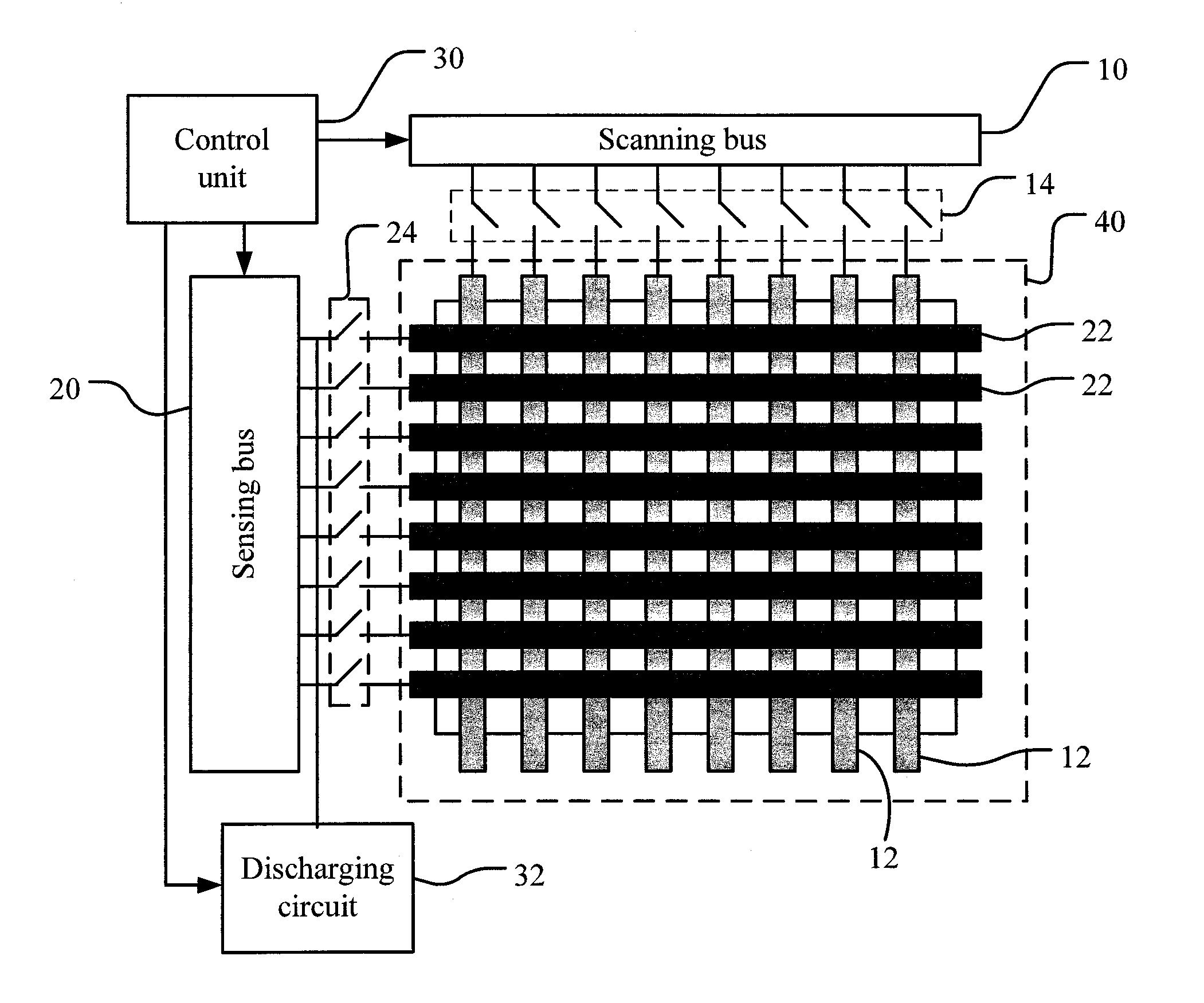
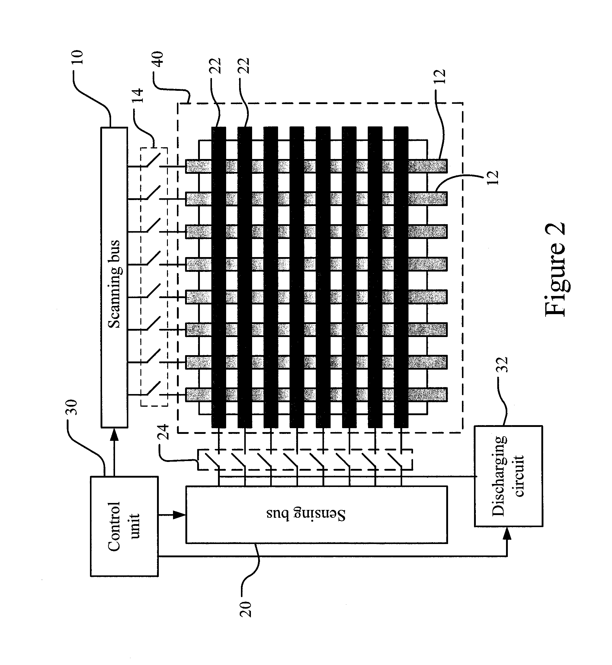
[0021]FIG. 2 shows a structural schematic diagram according to a preferred embodiment of the present invention. As shown in the Figure, the touch panel with a discharging function according to the present invention comprises a scanning bus 10, a sensing bus 20, a control unit 30, and a discharging circuit 32. The scanning bus 10 is used for scanning a touch frame 40. The sensing bus 20 interleaves with the scanning bus 10, and senses at least a touched location on the touch frame 40. Namely, the scanning bus 10 is coupled to a plurality of scanning lines 12; the sensing bus 20 is coupled to a plurality of sensing lines 22. The plurality of scanning lines 12 of the scanning bus 10 interleave with the plurality of se...


PUM


Abstract

The present invention relates to a touch panel with a discharging function, which comprises a scanning bus, a sensing bus, a control unit, and a discharging circuit. The scanning bus is used for scanning a touch frame. The sensing bus interleaves with the scanning bus, and senses at least a touched location on the touch frame. The control unit is coupled to the scanning bus and the sensing bus 20′ for controlling them. The discharging circuit is coupled to the sensing bus or/and the scanning bus, and is controlled by the control unit for releasing the charges at the touched location or/and on the relevant path between the touched location and the buses. Thereby, by using a discharging circuit for releasing charges on the parasitic capacitor, the parasitic capacitance effect is avoided. Hence, the sensing accuracy of the touch panel is increased.

Description

FIELD OF THE INVENTION[0001]The present invention relates generally to a touch panel, and particularly to a touch panel with a discharging function.BACKGROUND OF THE INVENTION[0002]Recently, various electronic products are developed in the trend of easier operations, small volume, and large displays. In particular, portable electronic products are demanding severely in volume and display size. Thereby, many electronic products integrate touch panels and liquid-crystal displays for saving the space required by keyboards or operational keys, and hence expanding the area available for displays.[0003]Currently, touch panels can be categorized into resistive, capacitive, infrared, and ultrasonic touch panels, and the resistive and capacitive panels are most popular. For capacitive touch panels, the feature of multi-point control provides more friendly operation modes, and thus is gradually favorable in the market. However, capacitive touch panels can only be operated by touching the pane...

Claims


Application Information

Patent Timeline
Patent Type & Authority Applications(United States)
IPC IPC(8): G06F3/041
CPCG06F3/041G06F3/045G06F3/044G06F3/04166G06F3/0446G06F3/0445
Inventor HUNG, CHIH-DEYEH, CHENG-CHUNGKUO, TING-LONG
Owner SITRONIX TECH CORP
Why Eureka
Try Eureka