Backlight device and display equipped with the device

Inactive Publication Date: 2010-12-23
SHARP KK
View PDF7 Cites 19 Cited by
  • Summary
  • Abstract
  • Description
  • Claims
  • Application Information

AI Technical Summary

Benefits of technology

[0023]The present invention can provide a backlight device that reduces the constraint on the placement of a circuit board in

Problems solved by technology

Moreover, the direct type backlight device has a hollow structure inside, and therefore is lightweight even if the size is increased.
Consequently, a relatively large space that accommodates the circuit boards

Method used


Image

  • Backlight device and display equipped with the device
  • Backlight device and display equipped with the device
  • Backlight device and display equipped with the device

Examples


embodiment 1

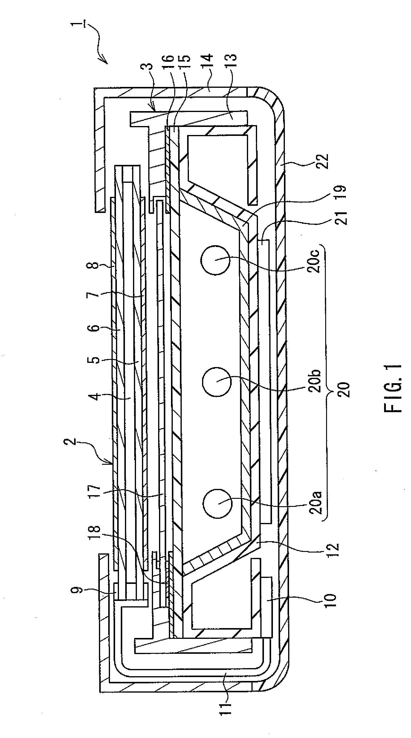
[0039]FIG. 1 is a schematic cross-sectional view showing a backlight device and a liquid crystal display device including the backlight device according to an embodiment of the present invention. As shown in FIG. 1, a liquid crystal display device 1 of this embodiment includes a liquid crystal panel 2 (display portion) and a backlight device 3. The liquid crystal panel 2 is placed with the upper side of FIG. 1 being identified as a viewer side (display surface side). The backlight device 3 is placed on the non-display surface side of the liquid crystal panel 2 (i.e., the lower side of FIG. 1) and irradiates the liquid crystal panel 2 with planar light.

[0040]The liquid crystal panel 2 includes a liquid crystal layer 4, a pair of transparent substrates 5, 6 that sandwich the liquid crystal layer 4, and polarizing plates 7, 8 that are provided on the outer surfaces of the transparent substrates 5, 6, respectively. The liquid crystal panel 2 also includes a driver 9 for driving the liqu...

embodiment 2

[0065]Next, a display device according to Embodiment 2 of the present invention will be described by way of example in which a lighting circuit for lighting lamps has a different circuit board configuration.

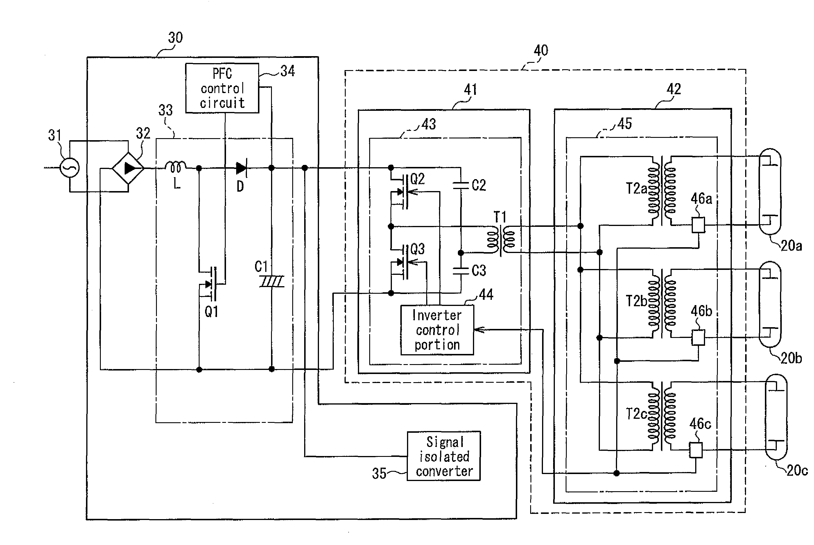
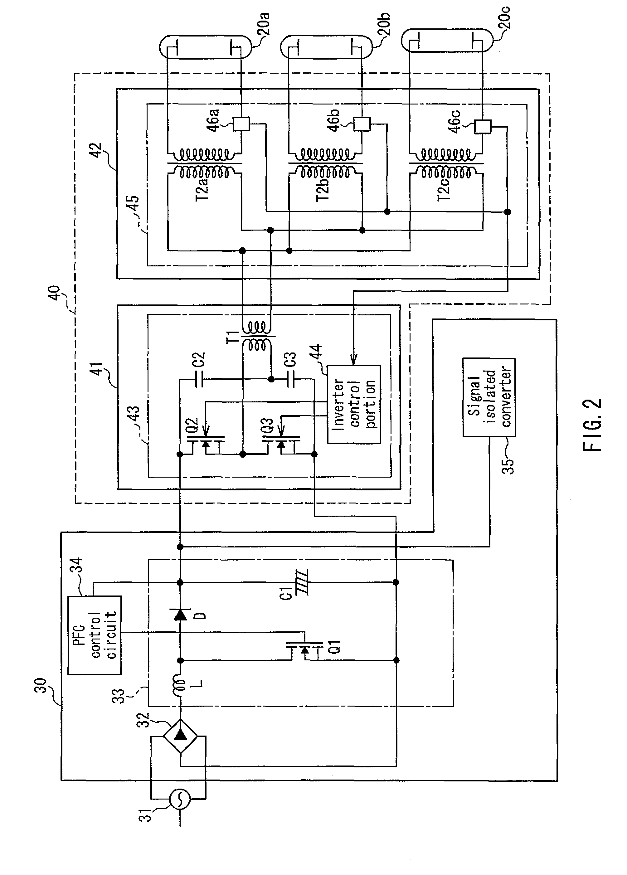
[0066]FIG. 3 is a block diagram showing the configuration of the lighting circuit of the backlight device used in the display device according to Embodiment 2 of the present invention. The liquid crystal display device of this embodiment differs from that of Embodiment 1 only in the configuration of the inverter unit of the lighting circuit, and other configurations of the liquid crystal display device and the configuration of the backlight device are the same as those in Embodiment 1. Therefore, the representation and the detailed explanation will not be repeated.

[0067]As shown in FIG. 3, the lighting circuit of the backlight device used in the liquid crystal display device of Embodiment 2 includes a power supply unit disposed on a power supply circuit board 30 and an inverter u...


PUM


Abstract

The present invention provides a backlight device that can ensure the margin for design of the placement of a circuit board by simplifying the configuration of a lighting circuit of a lamp and reducing the size of the circuit board on which circuit components are mounted, and a display device using the backlight device. The backlight device includes a lamp (20) and a lighting circuit (21) that generates a lighting drive voltage to light and drive the lamp (20). The lighting circuit (21) includes the following: a direct-current power supply circuit (33) that generates a direct-current voltage from an input voltage; an inverter drive circuit (43) that converts the direct-current voltage output from the direct-current power supply circuit (33) into a high frequency voltage; and a booster portion (T2) that boosts the high frequency voltage output from the inverter drive circuit (43) to a lighting drive voltage of the lamp (20). The direct-current power supply circuit (33) and the inverter drive circuit (43) are disposed on different circuit boards.

Description

TECHNICAL FIELD[0001]The present invention relates to a backlight device that provides a lighting drive voltage of a lamp by an inverter circuit, and a display device using the backlight device.BACKGROUND ART[0002]In recent years, a liquid crystal display device characterized by low power consumption, small thickness, lightweight, etc. has been widely used as a display device for televisions. A liquid crystal panel, i.e., a display element used in a display portion of the liquid crystal display device is a so-called non-emission type display element that does not emit light itself. Therefore, a light source called a backlight device is provided generally on the back of the liquid crystal panel, and the degree of transmission of light emitted from the backlight device is controlled by a liquid crystal layer, so that images are displayed.[0003]The backlight device of the liquid crystal display device is required to illuminate the entire surface of the image display region of the liqui...

Claims


Application Information

Patent Timeline
IPC IPC(8): G06F3/038H05B41/36
CPCH05B41/2827G02F1/133615G02F1/133604
Inventor CHO, SHIYOSHI
Owner SHARP KK
Why Eureka
Try Eureka