Electromagnetic Radiation Detector

a detector and electromagnetic radiation technology, applied in the field of electromagnetic radiation sensor, can solve the problems of high cost and expensive conversion, and achieve the effect of easy chang

Inactive Publication Date: 2010-12-23
ARNDT DONALD J
View PDF5 Cites 14 Cited by
  • Summary
  • Abstract
  • Description
  • Claims
  • Application Information

AI Technical Summary

Benefits of technology

[0012]The sensor circuit may be a PCB module that plugs into the EMR detector. This configuration allows the frequency spectrum of the EMR detector to be easily changed to a desired EMR frequency band.

Problems solved by technology

This existing technology requires expensive conversions and the devices are limited to those portions of the frequency spectrum inherently designed in the instrument, so one has to purchase another instrument at great costs to detect another portion of the spectrum.

Method used


Image

  • Electromagnetic Radiation Detector
  • Electromagnetic Radiation Detector
  • Electromagnetic Radiation Detector

Examples


embodiment 600

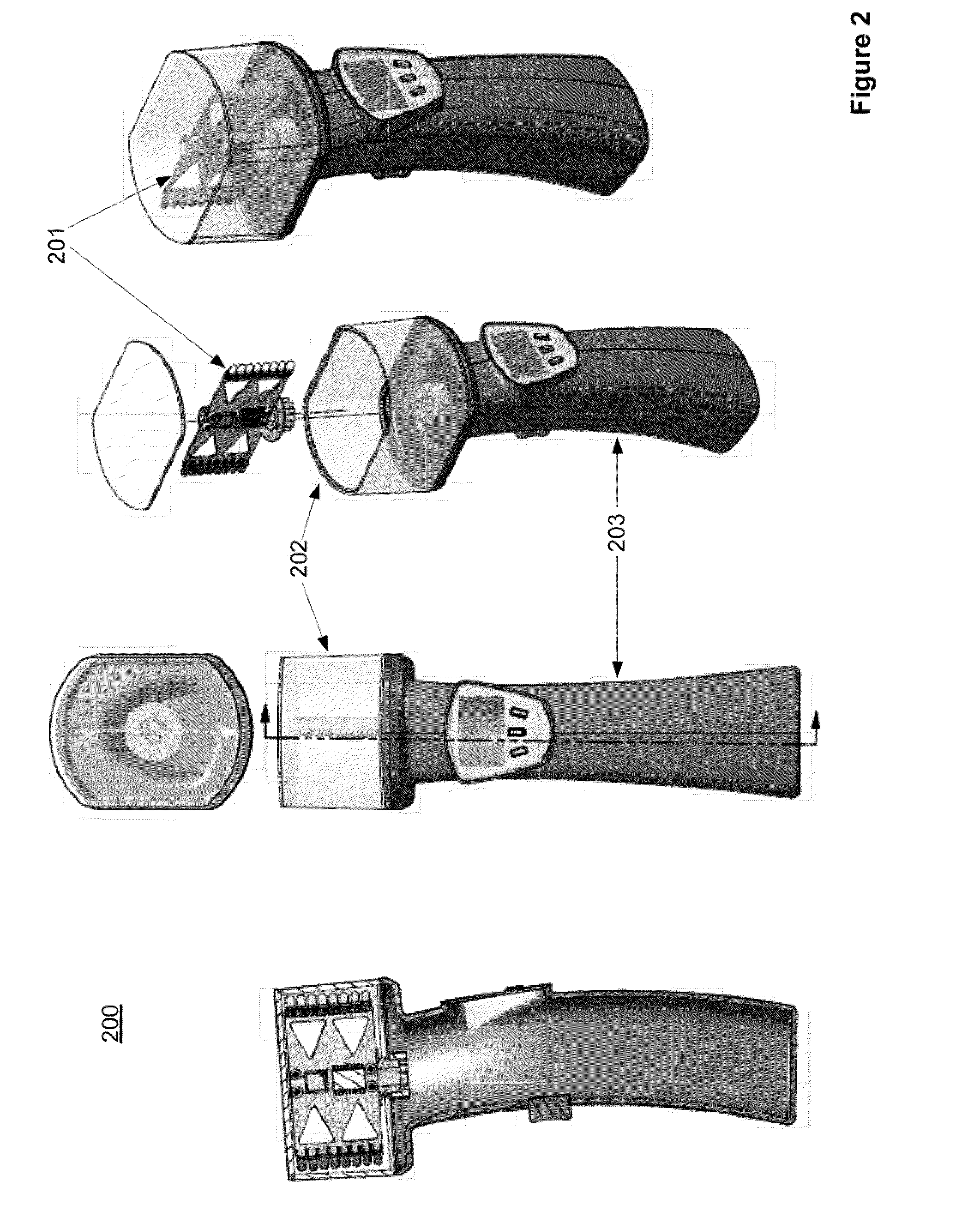
[0074]The multiplexed and synchronized data are then coupled to a rotate-oscillate data on / off block 602. The oscillate data on / off block 602 also comprises magnetic and / or optical circuits and / or other wireless technology that provides bi-lateral communications between the sensor circuit PCB 611 and the handle PCB 612. Hence, communications is facilitated without the use of wires. Per embodiment 600, the communication may be implemented by magnetic induction and / or by light transmission, as illustrated by circuits 607. The communications comprises image information resulting from the EMR signals and control data. The mutual induction also supports power coupling in order to power the sensor circuit PCB 611.

[0075]The multiplexed and synchronized data is received in the block 603 which is an equivalent function as block 602. The multiplexed and synchronized data is then coupled to an in-handle microprocessor and memory, block 604. Block 604 also comprises drivers for USB and hard dri...

embodiment 750

[0078]Per FIGS. 7a and 7b, for the non-hand-held device, the viewer's head and the sensor circuit PCB 702 rotate 360 degrees relative to a base portion or base unit 706. The base unit 706 is the base portion for this embodiment. The base unit 706 has some of the same functions as the handle of the hand-held device. As shown in FIGS. 7a and 7b, 700 is the top view of the non-hand-held device and 750 is the side view of the non-hand-held device. The viewer's head comprises an outer surface 701 and a removable top 703. The outer surface 701 of the device is a clear, frosted, or lenticular (bug's eye) surface. The outer surface 701 is stationary relative to the base unit 706. The sensor circuit PCB 702 rotates with sensors on one or vertical edges. For a non-hand-held embodiment, there are no LEDs. As shown in embodiment 750, there is a removable top 703 that may be removed when the viewer's head is not spinning so the sensor circuit PCB 702 may be removed and replaced.

[0079]The base un...


PUM


Abstract

A device implemented with the present invention senses and converts unseeable electromagnetic (EM) energy such as high frequency radio, infrared, ultraviolet, etc. to an image in the human visual spectrum (red to violet—i.e. the rainbow). The size of the image and quality of the image is improved by rotating or oscillating the sensors in order to scan a broader array of electrometric energy.
The electromagnetic radiation detector (EMR) comprises: a sensor circuit that generates EMR signals of the scanned electromagnetic energy of the desired band of electromagnetic spectrum. The EMR detector further comprises processors that convert the EMR signals into image data that is used to generate the visible image of the scanned electromagnetic energy; and a motor that allows the sensor circuit to scan the electromagnetic energy. The sensor circuit may be a plug-in PCB module to allow ready selection of the desired frequency band.

Description

PRIORITY CLAIM[0001]This application claims benefit of and hereby incorporates by reference provisional patent application Ser. No. 61 / 219,729, entitled “EMR Detector,” filed on Jun. 23, 2009, by inventor Donald J. Arndt.FIELD OF THE INVENTION[0002]This invention generally relates to sensors of electromagnetic radiation, and more particularly to apparatus and methods of converting electromagnetic radiation to visible light.BACKGROUND OF THE INVENTION[0003]There are a number of devices that are capable of sensing electromagnetic radiation and converting that energy into an information source. For example, there are devices that sense the unseen energy and then electronically convert the “electromagnetic energy” to the visible spectrum and display the image on a sensitive screen or video tube (see FIG. 1). These devices are use in a wide variety of applications including detection of the following environments; laptop hotspot, overheating circuit breaker, very hot pipe or wiring under...

Claims


Application Information

Patent Timeline
Patent Type & Authority Applications(United States)
IPC IPC(8): H04N5/30
CPCH04N5/2252H04N5/2253H04N5/332H04N5/33H04N5/2259H04N23/58H04N23/51H04N23/54H04N23/11
Inventor ARNDT, DONALD J.
Owner ARNDT DONALD J
Why Eureka
Try Eureka