Annular Capacitor with power conversion components arranged and attached in manners uniquely allowed by the ring shaped form factor

a technology of power conversion components and annular capacitors, which is applied in the direction of wound capacitors, fixed capacitor details, fixed capacitors, etc., can solve the problems of low inductance and reduce the non-uniformity of current density within the capacitor, so as to improve the reliability, reduce heat dissipation, and increase the long-term reliability of the dc link capacitor

Inactive Publication Date: 2010-12-23
SBELECTRONICS
View PDF6 Cites 14 Cited by
  • Summary
  • Abstract
  • Description
  • Claims
  • Application Information

AI Technical Summary

Benefits of technology

The present invention has several technical advantages. Firstly, it has low heat dissipation for a given switching current. Secondly, it increases the long term reliability of the DC Link capacitor for any given capacitor current. Thirdly, it has a very low Effective Series Inductance (ESL), which reduces voltage overshoot seen by the switch devices when they turn off. Fourthly, it has a very low Effective Series Resistance (ESR), which results in less heating and lower ESR. Fifthly, it simplifies the connection bus structure, making it possible for weight, volume, and cost reduction.

Problems solved by technology

The technical problem addressed in this patent text is the need for a DC link capacitor in power conversion technology to reduce impedance, remove noise, and store energy for short-term interruption of the DC source. However, the current design of the capacitor results in disproportionate heating and reduced reliability due to the hottest spot in the capacitor. The patent proposes a solution to improve the long-term reliability of the capacitor.

Method used


Image

  • Annular Capacitor with power conversion components arranged and attached in manners uniquely allowed by the ring shaped form factor
  • Annular Capacitor with power conversion components arranged and attached in manners uniquely allowed by the ring shaped form factor
  • Annular Capacitor with power conversion components arranged and attached in manners uniquely allowed by the ring shaped form factor

Examples


Embodiment Construction

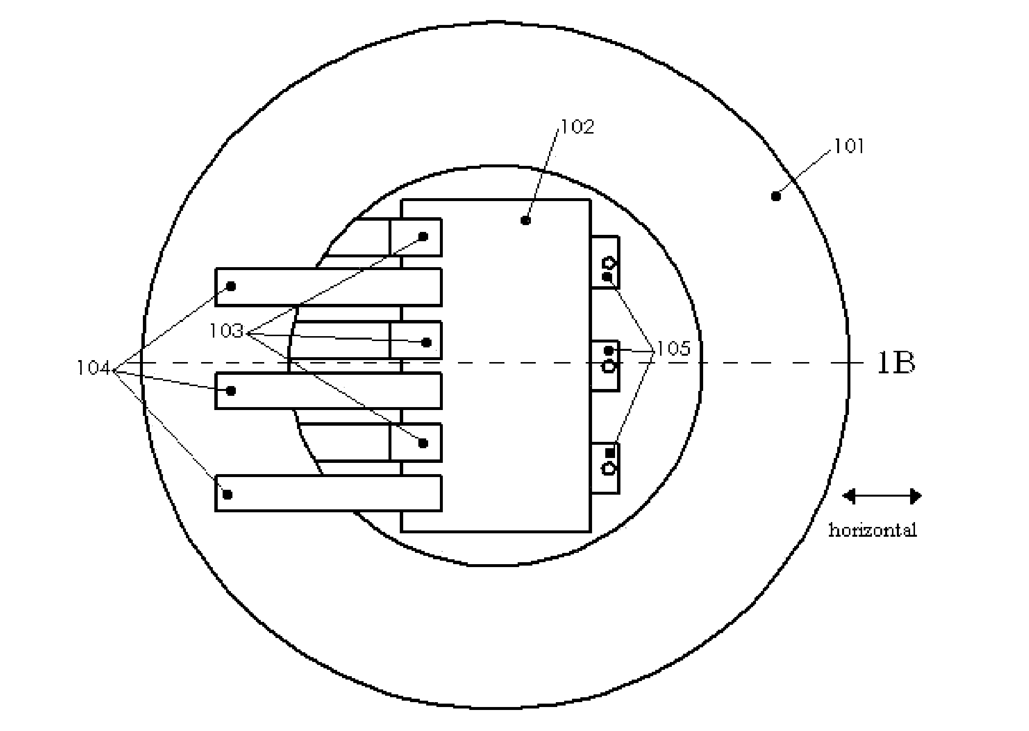
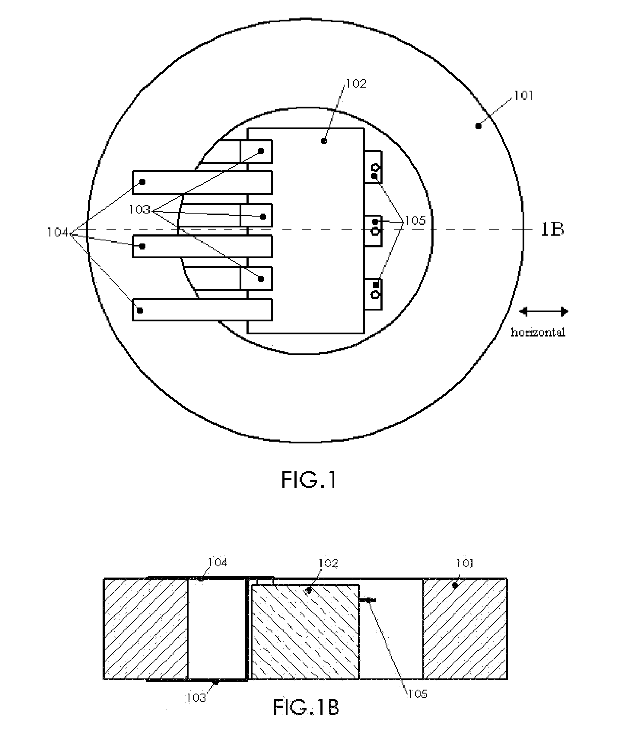
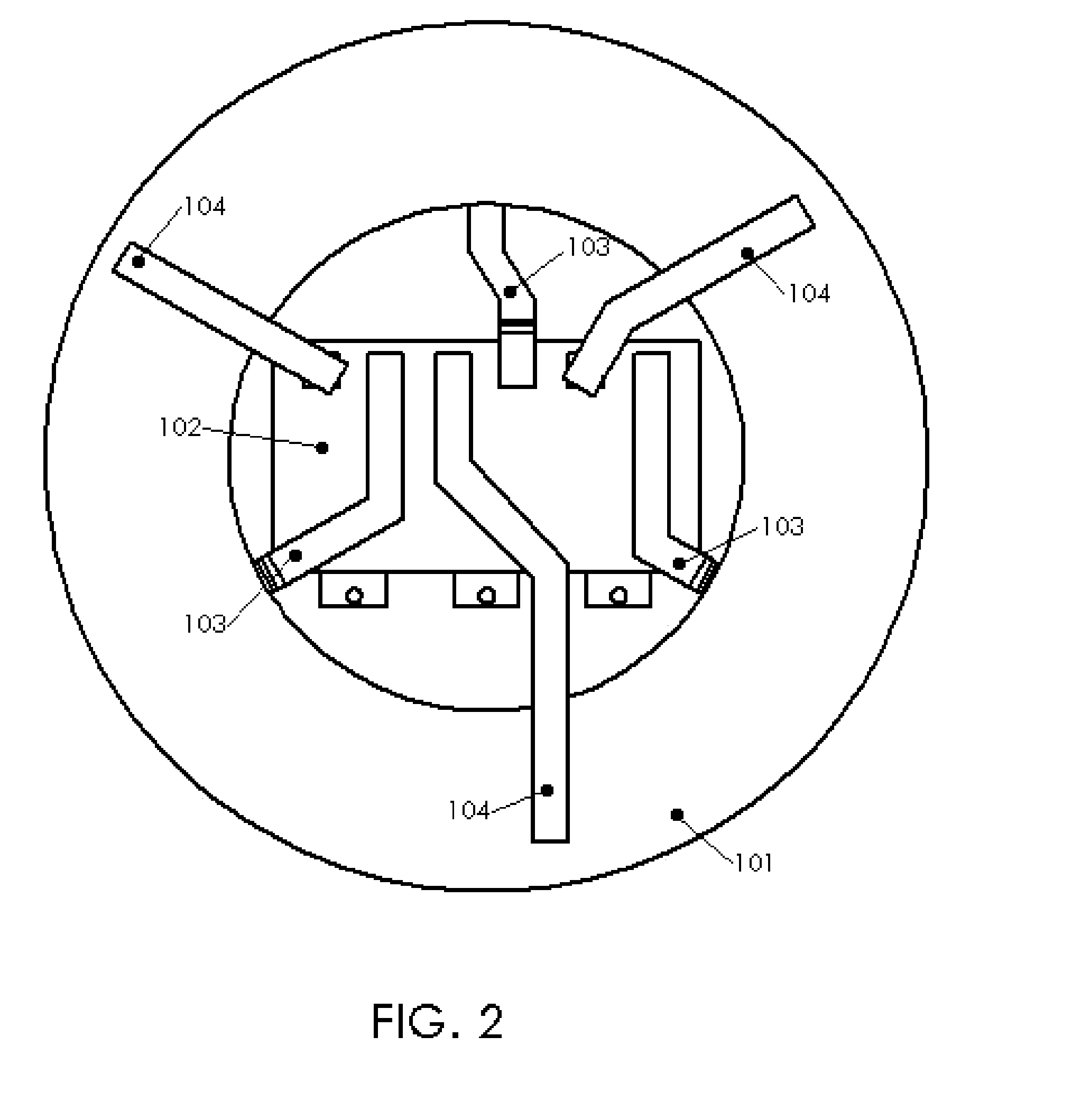
[0035]A metallized film polymeric annular capacitor with a single power conversion component is shown in FIG. 1. The annular capacitor body 101 has a variable center hole radius that can be made to fit a power conversion component 102 to exact specifications with the necessary space for the upper terminals 104, lower terminals 103, and output terminals 105 of the component. In FIG. 1 the terminals are positioned for the shortest path possible with a typical, commercially available power conversion component. The outer radius and thickness of the annular capacitor can then be selected to achieve the desired capacitance for the power conversion application. The thickness of the annular capacitor is addressed in FIG. 1B. The depth of the annular capacitor 101 is made to match the height of the power conversion component 102 so that the terminals 103 and 104 can maintain the shortest distance for connection to the capacitor, and thereby the lowest connection inductance possible for this...


PUM


Abstract

The formation of an assembled unit consisting of an annular capacitor [a wound, metallized dielectric capacitor in the shape of a closed path ring] with other power conversion components arranged and attached in manners uniquely allowed by the ring design will allow higher density converter designs [power/unit volume]. The resulting short connection paths between the capacitor element and the switching semiconductors also provide a very low inductance path that minimizes voltage spikes on the switching semiconductors as a result of turn-off di/dt. The capacitor serves as a short time current source and sink for the switching semiconductors. With the described configuration the RMS current seen by the capacitor can be made more volumetrically uniform enabling more uniform capacitor rise. The single capacitor configured as described also mitigates bus resonance problems often observed in prior art when multiple discrete capacitors are connected in parallel.

Description


Claims


Application Information

Patent Timeline
Owner SBELECTRONICS
Why Eureka
Try Eureka