Objective lens, optical pickup, and optical disc apparatus

a technology of optical disc and objective lens, which is applied in the direction of lenses, record information storage, instruments, etc., can solve the problems of reducing the quality of reproduced signals, increasing production cost and the size of optical pickups, and affecting the operation of optical discs. , to achieve excellent recording and reproduction characteristics, the effect of preventing the deterioration of recording and reproduction characteristics and preventing the instability of servo control

Active Publication Date: 2010-12-23
SONY CORP
View PDF10 Cites 14 Cited by
  • Summary
  • Abstract
  • Description
  • Claims
  • Application Information

AI Technical Summary

Benefits of technology

[0018]With the embodiments of the present invention, the diffraction section enables the single optical lens to appropriately focus a corresponding light beam on the signal recording surface of each of three types of optical discs. Moreover, servo control is prevented from becoming unstable owin

Problems solved by technology

However, because the optical pickup has two objective lenses, each of the objective lenses may not be mounted on a lens holder of an actuator at an appropriate angle.
Therefore, the angles between the objective lens and the optical disc may not be optimal, so that the quality of a reproduced signal may be reduced.
Therefore, the production cost and the size of the optical pickup increase.
Moreover, the weight of the actuator increases because it is necessary to mount two objective lenses to the actuator for driving the objective lenses.
However, such optical pickups that have been developed, which use a single obje

Method used


Image

  • Objective lens, optical pickup, and optical disc apparatus
  • Objective lens, optical pickup, and optical disc apparatus
  • Objective lens, optical pickup, and optical disc apparatus

Examples


Embodiment Construction

[0057]Hereinafter, best modes for carrying out the invention will be described in the order of the sections listed below.

1. Overall Structure of Optical Disc Apparatus

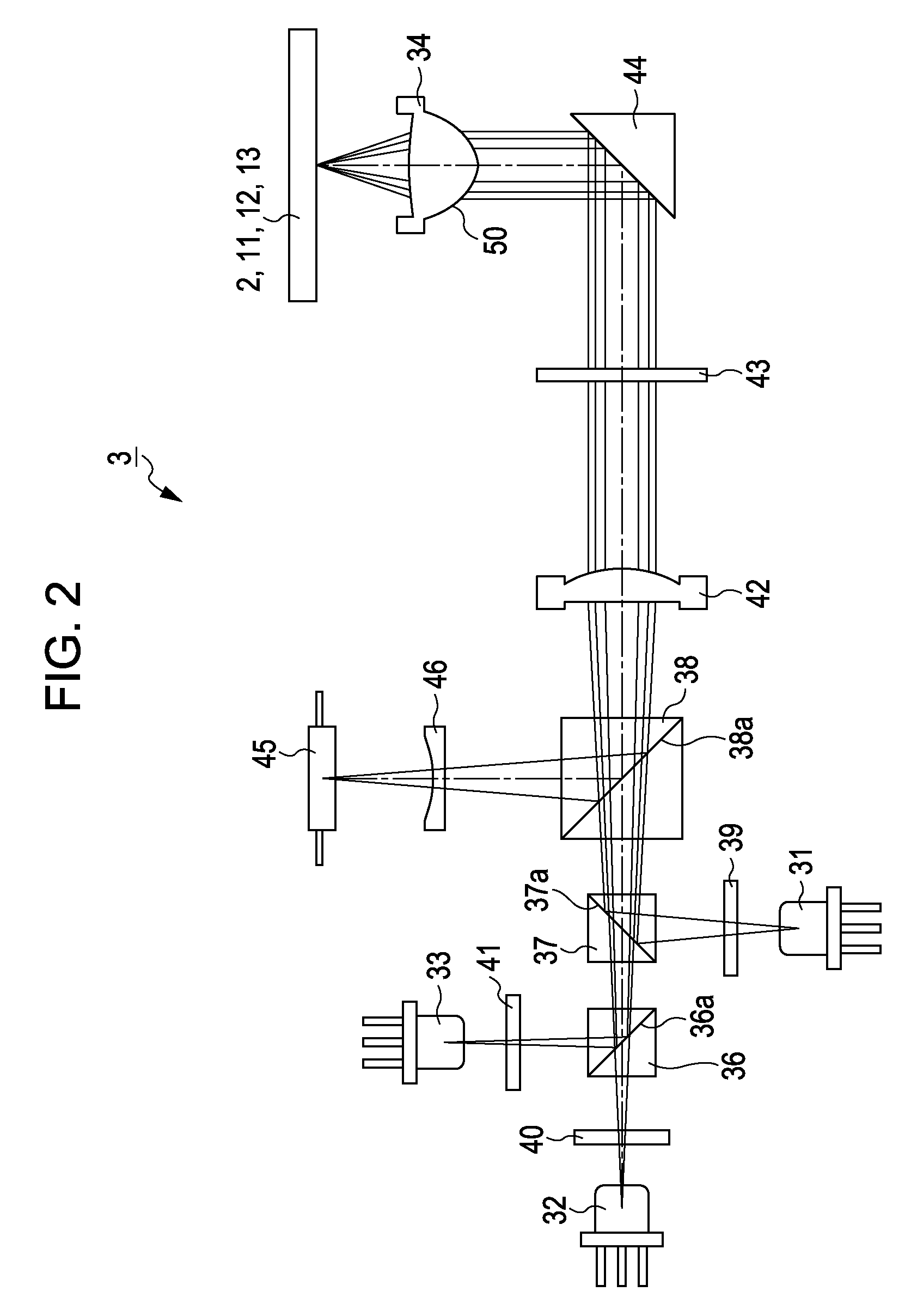
2. Overall Structure of Optical Pickup

[0058]3. Objective Lens according to Embodiment of the Invention

4. Objective Lens according to Another Embodiment of the Invention

5. Technique for Preventing Increase in Unwanted Diffracted Light due to Variations in Temperature and Wavelength

[0059]6. Example of Diffraction Section used in Optical Pickup according to Embodiment of the Invention (modification of 3)

7. Another Example of Diffraction Section used in Optical Pickup according to Embodiment of the Invention (modification of 4)

8. Optical Pickup according to Embodiment of the Invention

9. Optical Pickup according to Another Embodiment of the Invention

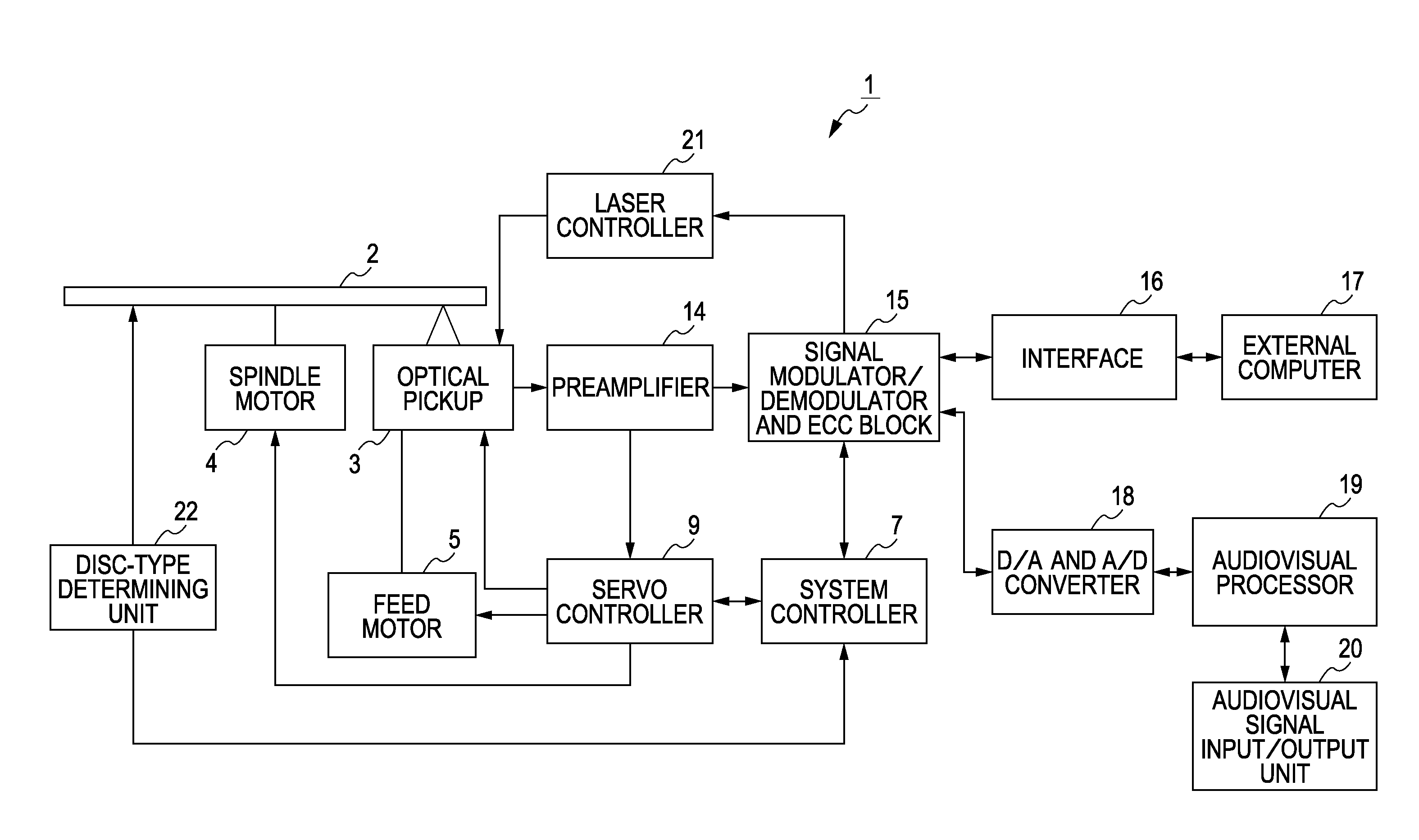
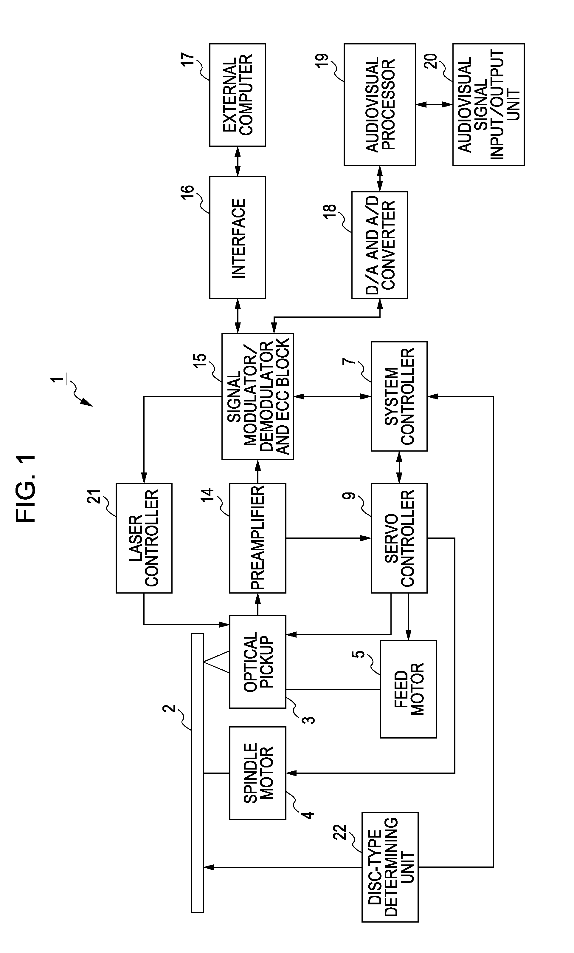
[1. Overall Structure of Optical Disc Apparatus]

[0060]Hereinafter, an optical disc apparatus including an optical pickup according to an embodiment of the present invention will...


PUM


Abstract

Provided is an objective lens for selectively focusing each of light beams having three wavelengths λ1, λ2, and λ3 on a signal recording surface of a corresponding optical disc, the wavelengths λ1, λ2, and λ3 satisfying at least a relationship λ1<λ2<λ3, the objective lens including a diffraction section disposed on an entry-side surface thereof, the diffraction section including a first region disposed in an innermost radius portion, a second region disposed outside the first region, and a third region disposed outside the second region, the first to third regions being formed so that an aperture of the light beams are appropriately limited, the first region including a staircase-like diffractive structure having a certain number of levels configured so that diffracted light of a predetermined order has the highest diffraction efficiency and optical-path-difference phase amounts for the levels of the diffractive structure has a certain relationship.

Description

BACKGROUND OF THE INVENTION[0001]1. Field of the Invention[0002]The present invention relates to an objective lens used in an optical pickup for recording information signals to and / or reproducing information signals from three different types of optical discs. The present invention also relates to an optical disc apparatus including the optical pickup.[0003]2. Description of the Related Art[0004]In recent years, an optical disc in a next-generation optical disc format that allows high-density recording and reproduction of signals using a light beam having a wavelength of about 405 nm emitted from a blue-violet semiconductor laser has been proposed (hereinafter referred to as a “high-density-recording optical disc”). Such a high-density-recording optical disc has a thin cover layer for protecting a signal recording layer. The cover layer has a thickness of, for example, 0.1 mm.[0005]When producing an optical pickup for such a high-density-recording optical disc, it is desirable that...

Claims


Application Information

Patent Timeline
IPC IPC(8): G11B7/135G02B5/18
CPCG02B3/08G02B5/1814G02B5/1895G11B2007/0006G11B7/1353G11B7/1374G11B7/13922G02B27/4238
Inventor YASUI, TOSHIFUMI
Owner SONY CORP
Why Eureka
Try Eureka