MEMS microphone

Active Publication Date: 2010-12-23
AAC ACOUSTIC TECH (SHENZHEN) CO LTD +1
View PDF12 Cites 108 Cited by
  • Summary
  • Abstract
  • Description
  • Claims
  • Application Information

AI Technical Summary

Benefits of technology

[0006]Other features and advantages of the present invention will become more apparent to those skilled

Problems solved by technology

While these disclosures have reduced the size of the device, they have not disclosed how to protect the transducer from outside interferences.
For instance, transducers of this type a

Method used


Image

  • MEMS microphone
  • MEMS microphone
  • MEMS microphone

Examples


Embodiment Construction

[0010]Reference will now be made to describe the exemplary embodiment of the present invention in detail.

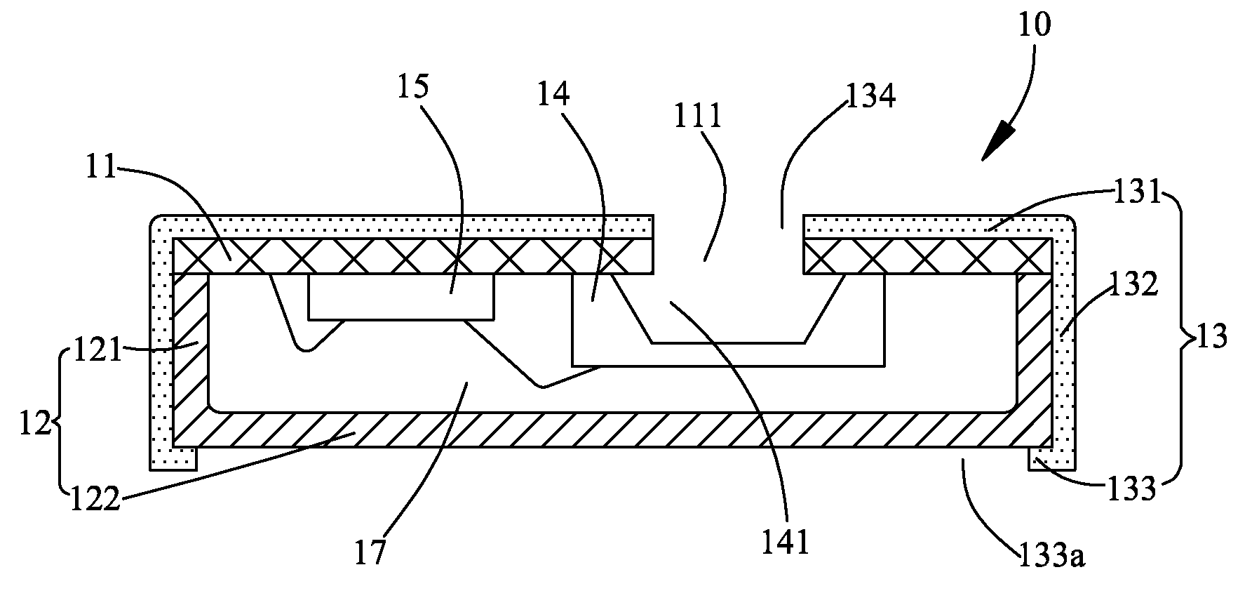
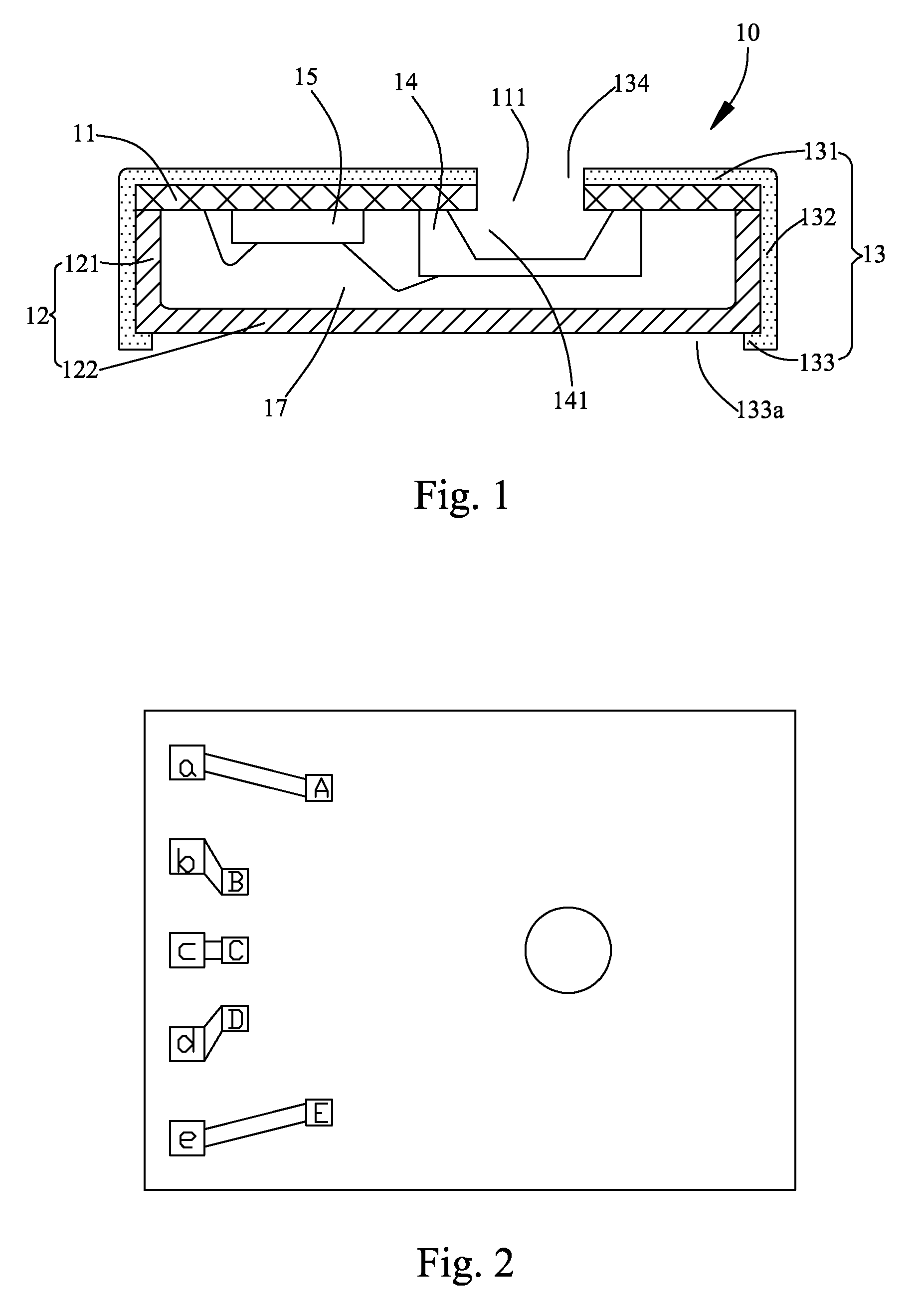
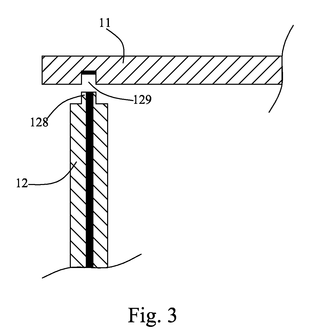
[0011]Referring to FIG. 1, a MEMS microphone 10 generally includes a cover 11, a housing 12, and a number of transducers. In this embodiment, the transducers include a MEMS die 14 and a controlling chip 15. The combination of the cover 11 and the housing 12 forms a cavity 17 for receiving the MEMS die 14 and the controlling chip 15. The cover 11 may be a printed circuit board. The MEMS die 14 defines a back volume 141. The cover 11 further defines an acoustic hole 111, and the MEMS die 14 is mounted on the cover 11 overlapping at least a portion of the acoustic hole 111. The back volume 141 of the MEMS die 14 is communicated with the acoustic hole 111.

[0012]The housing 12 includes a base 122 and a sidewall 121 extending perpendicularly from the base 122. The sidewall 121 connects with the cover 11.

[0013]The MEMS microphone 10 further includes a conductive case 13 covering the cov...


PUM


Abstract

A MEMS microphone includes a cover, a housing engaging with the cover for forming a cavity, at least one transducer accommodated in the cavity, and a conductive case covering the cover and the sidewall of the housing. The housing includes a cover and a sidewall extending from the base. The conductive case defines a first part covering the cover, a second part extending from the first part for covering the sidewall and a third part perpendicularly extending from the second part for covering a periphery part of the base, the third part forming an opening.

Description

1. FIELD OF THE INVENTION[0001]The present invention relates generally to microphones. More particularly, this invention relates to a microelectromechanical (MEMS) microphone.2. DESCRIPTION OF RELATED ART[0002]There have been a number of disclosures related to building microphone elements on the surface of a silicon die. Certain of these disclosures have come in connection with the portable device field for the purpose of reducing the size of the device. While these disclosures have reduced the size of the device, they have not disclosed how to protect the transducer from outside interferences. For instance, transducers of this type are fragile and susceptible to physical damage. Furthermore, they must be protected from light and electromagnetic interferences. For these reasons, the silicon die must be shielded.[0003]Typically, such a MEMS microphone generally includes a MEMS die having a silicon substrate, a backplate arranged on the substrate, and a moveable diaphragm separated fr...

Claims


Application Information

Patent Timeline
IPC IPC(8): H04R3/00
CPCB81B7/0061B81B2201/0257H04R2201/003H04R1/06H04R1/04
Inventor WU, ZHI-JIANGCHEN, XING-FUSU, YONG-ZE
Owner AAC ACOUSTIC TECH (SHENZHEN) CO LTD
Why Eureka
Try Eureka