Combined-Type Lathe Tool

a cutter and combination technology, applied in the field of cutters of large machine tools, can solve the problems of heavy workload on high power input to these large machine tools, and the inability of conventional small cutters to stand vibration in the operation of such large machine tools, and achieve the effect of convenient operation

Inactive Publication Date: 2010-12-23
YING FAN ENTERPRISE
View PDF9 Cites 20 Cited by
  • Summary
  • Abstract
  • Description
  • Claims
  • Application Information

AI Technical Summary

Benefits of technology

[0009]It is an objective of the present invention to provide an inexpensive combinative cutter that is stable yet convenient in operation.

Problems solved by technology

The workloads on such large machine tools are heavy, and the power fed to these large machine tools is high.
Conventional small cutters cannot stand vibration in the operation of such large machine tools.
Should such a small cutter be used in such a large machine tool, not only the life of the small cutter would be shortened, but also the efficiency and precision of the operation would be affected.
A problem with the shank 50 is difficulty in positioning and moving the shank 50 because it is bulky and heavy.
This causes troubles in the operation and affects the efficiency and safety of the operation.
Moreover, the shank 50 is expensive for consuming a lot of material of which the price is skyrocketing.
It is difficult to align a jet of the cutting liquid to the new blade 56, thus jeopardizing the effects of the cooling and washing.

Method used


Image

  • Combined-Type Lathe Tool
  • Combined-Type Lathe Tool
  • Combined-Type Lathe Tool

Examples


Embodiment Construction

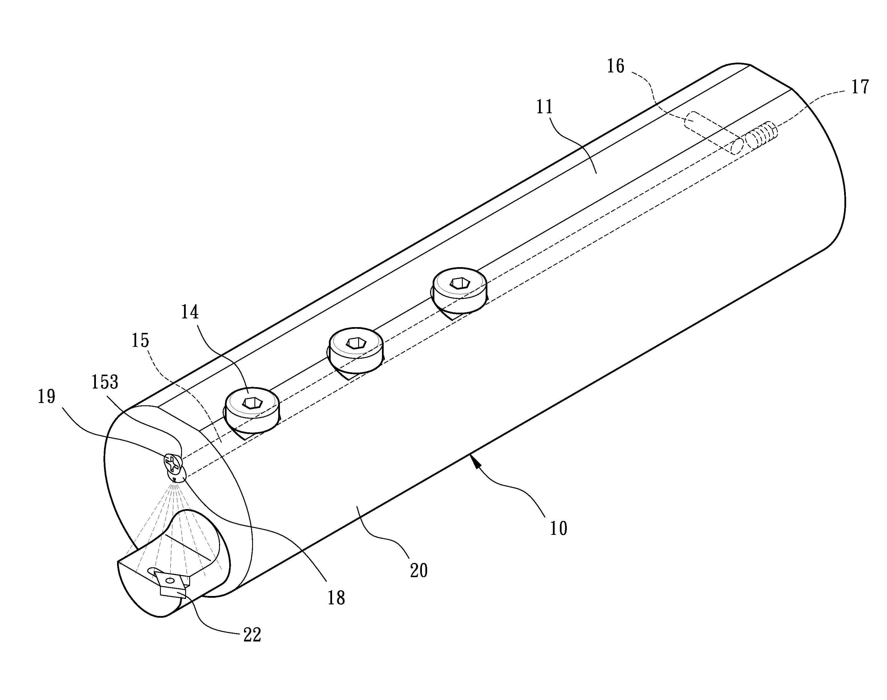
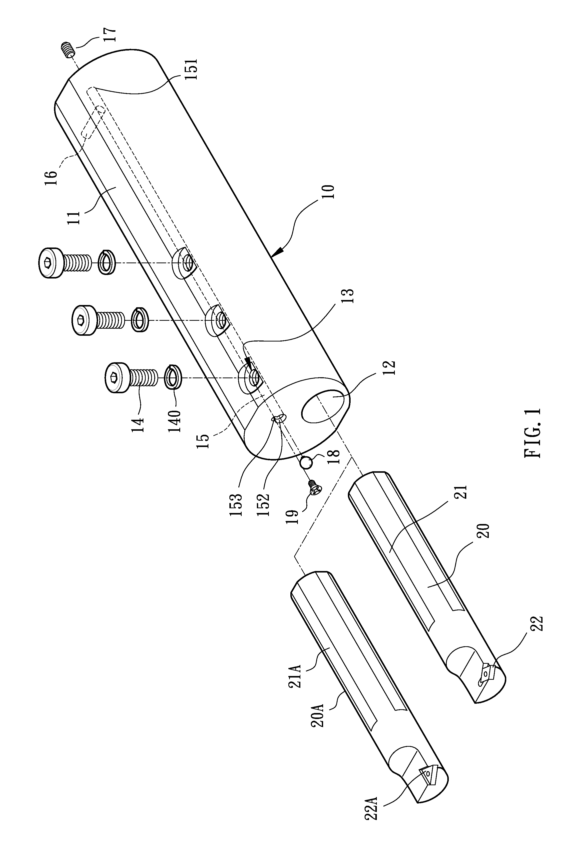
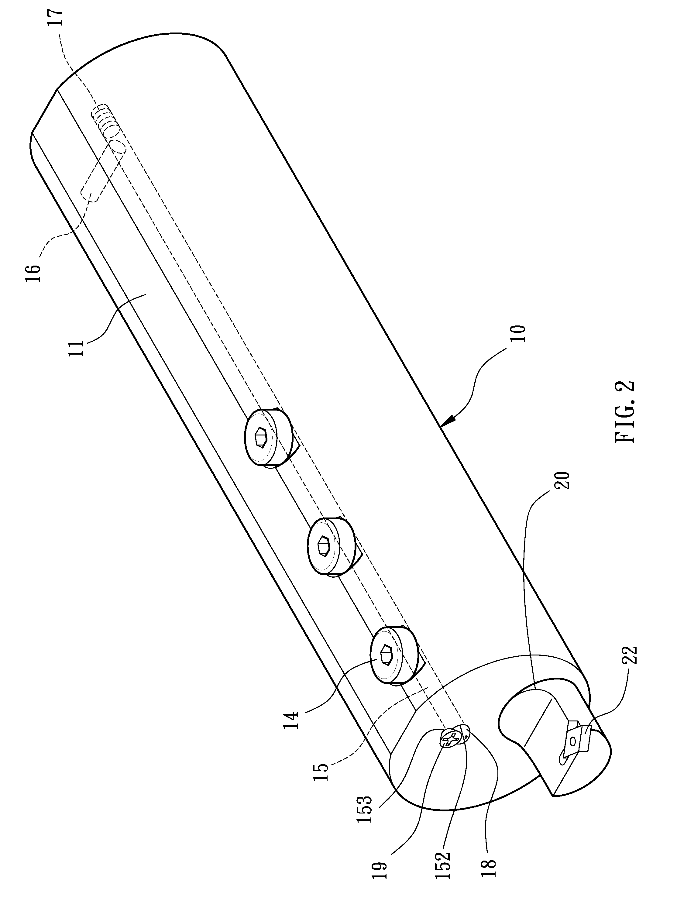
[0024]Referring to FIGS. 1 and 2, a combinative cutter includes a holder 10 and a shank 20 according to the preferred embodiment of the present invention. The shank 20 is located on the holder 10 eccentrically. The blade 22 is secured to the shank 20.

[0025]Referring to FIGS. 1 through 3, the holder 10 is cylindrical. The holder 10 includes, on the periphery, at least one planar face 11 with which the holder 10 can be located on a mount stably. An eccentric bore 12 is defined in an eccentric position at an end of the holder 10. Two screw holes 13 or more are defined in the periphery of the holder 10. The screw holes 13 are in communication with the eccentric bore 12. Thus, screws 14 can be driven in the eccentric bore 12 through the screw holes 13. Each of the screws 14 is inserted through a washer 140 to prevent accidental slacking thereof. The holder 10 includes a channel 15 defined therein. The holder 10 includes an aperture 16 defined therein opposite to the eccentric bore 12. Th...


PUM

PropertyMeasurementUnit
sizeaaaaaaaaaa
volumeaaaaaaaaaa

Abstract

A combinative cutter includes a holder, a shank, a blade and at least two screws. The holder includes an eccentric bore defined at an end and at least two screw holes in communication with the eccentric bore. The shank is inserted in the eccentric bore and formed with a planar face. The blade is attached to an end of the shank extending beyond the holder. The screws are driven through the screw holes and abutted against the planar face to keep the shank in the eccentric bore.

Description

BACKGROUND OF INVENTION[0001]1. FIELD OF INVENTION[0002]The present invention relates to a cutter of a large machine tool and, more particularly, to a combinative cutter.[0003]2. RELATED PRIOR ART[0004]Large components are needed in some fields. Such large components can be molded. For precision in size, such large components can further be processed with large machine tools such as gantry millers, gantry lathes and gantry grinders. The workloads on such large machine tools are heavy, and the power fed to these large machine tools is high. Conventional small cutters cannot stand vibration in the operation of such large machine tools. Should such a small cutter be used in such a large machine tool, not only the life of the small cutter would be shortened, but also the efficiency and precision of the operation would be affected.[0005]Conventionally, such large machine tools are equipped with specialized cutters. Referring to FIG. 5, there is shown a cutter of a large lathe for example...

Claims


Application Information

Patent Timeline
Patent Type & Authority Applications(United States)
IPC IPC(8): B23B27/10B23B29/12
CPCB23B27/007B23B29/046Y10T407/227B23B2250/12Y10T407/14B23B31/1075
Inventor LIN, KUO-CHI
Owner YING FAN ENTERPRISE
Why Eureka
Try Eureka