Surface acoustic wave device

a surface acoustic wave and acoustic wave technology, applied in piezoelectric/electrostrictive/magnetostrictive devices, impedence networks, piezoelectric/electrostriction/magnetostriction machines, etc., can solve disadvantageous ruptures in wiring lines at three-dimensional wiring portions, and achieve simplified manufacturing processes, prevent flux, and reduce the effect of material variety

Active Publication Date: 2010-12-30
MURATA MFG CO LTD
View PDF6 Cites 16 Cited by
  • Summary
  • Abstract
  • Description
  • Claims
  • Application Information

AI Technical Summary

Benefits of technology

[0018]Preferably, the surface acoustic wave device according to a preferred embodiment of the present invention further includes a protective layer composed of synthetic resin stacked on a side of the cover member opposite to the supporting member. Since the protective layer does not allow flux to pass therethrough, flux can be prevented from flowing into the hollow space during mounting of the surface acoustic wave device.
[0019]Preferably, the protective layer is composed of the same material as the supporting member. With this, the variety of materials can be reduced, and at the same time, manufacturing processes can be simplified.
[0020]The surface acoustic wave device according to a preferred embodiment of the present invention includes the supporting member so as to enclose the three-dimensional wiring portion in which the first and second wiring lines intersect with each other with the insulating layer interposed therebetween. As a result, the three-dimensional wiring portion faces the space enclosed by the piezoelectric substrate, the supporting member, and the cover member. Since the supporting member is not in contact with both the first and second wiring lines at the three-dimensional wiring portion, the first and second wiring lines are less susceptible to stress caused by a difference in the coefficients of linear expansion between the supporting member and the insulating layer. As a result, ruptures do not easily occur in the first and second wiring lines at the three-dimensional wiring portion.
[0021]Therefore, ruptures in the first and second wiring lines can be reliably prevented even when, for example, the supporting member and the cover member are formed of synthetic resin layers so as to reduce the thickness of the device and, at the same time, even when the insulating layer at the three-dimensional wiring portion is composed of a material that differs from that of the supporting member in view of reducing the parasitic capacitance.
[0022]Accordingly, ruptures at the three-dimensional wiring portions of the surface acoustic wave device can be reliably prevented in accordance with various preferred embodiments of the present invention so as to increase the reliability of the surface acoustic wave device.

Problems solved by technology

However, when the piezoelectric substrate is commonly used for a plurality of surface acoustic wave elements having a structure with which the size and the thickness of the devices can be reduced as in the surface acoustic wave device 101 described in Japanese Unexamined Patent Application Publication No. 2006-217226, ruptures disadvantageously occur in wiring lines at the three-dimensional wiring portions.

Method used


Image

  • Surface acoustic wave device
  • Surface acoustic wave device
  • Surface acoustic wave device

Examples


Embodiment Construction

[0032]The present invention will now be made clear by descriptions of specific preferred embodiments with reference to the drawings.

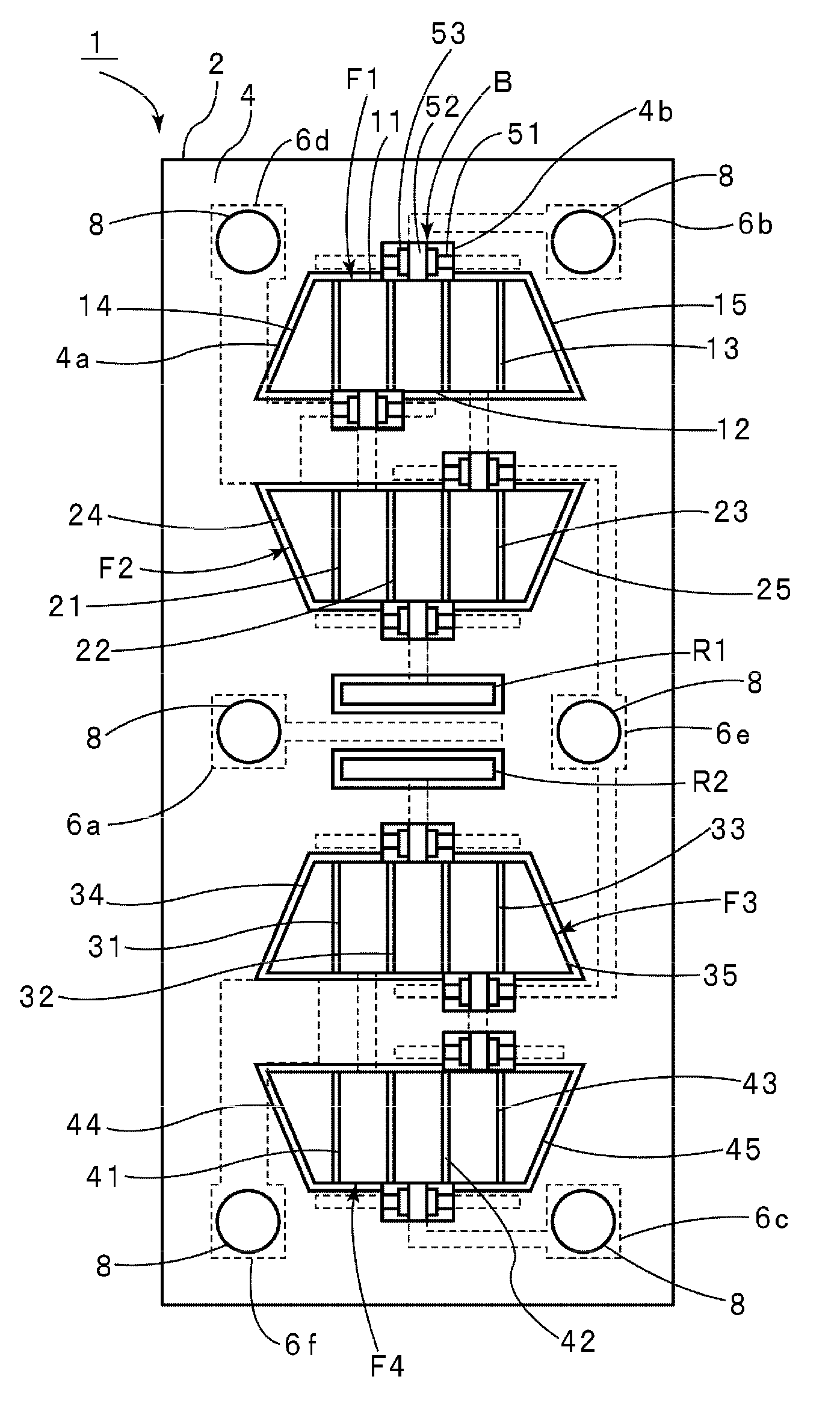
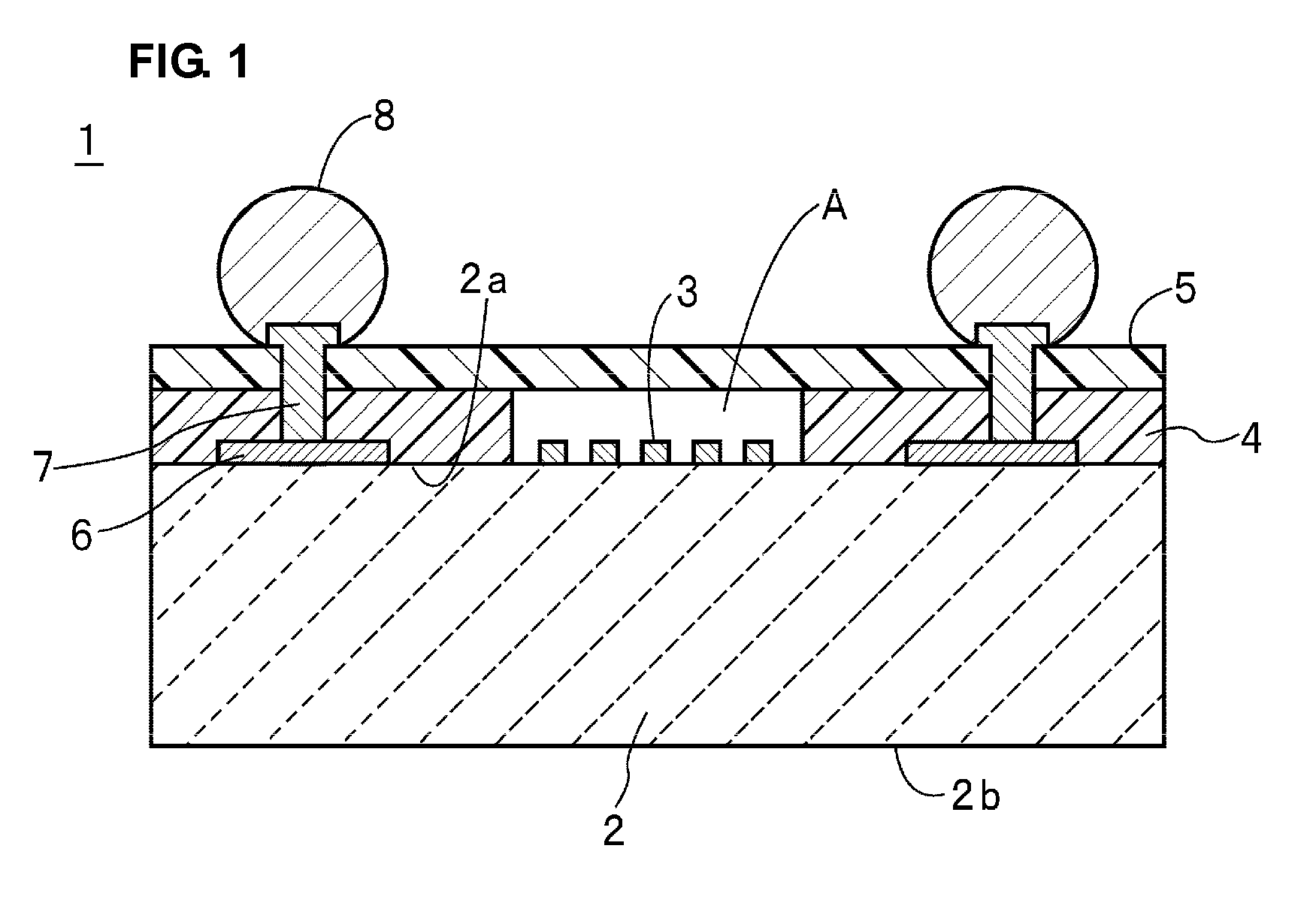
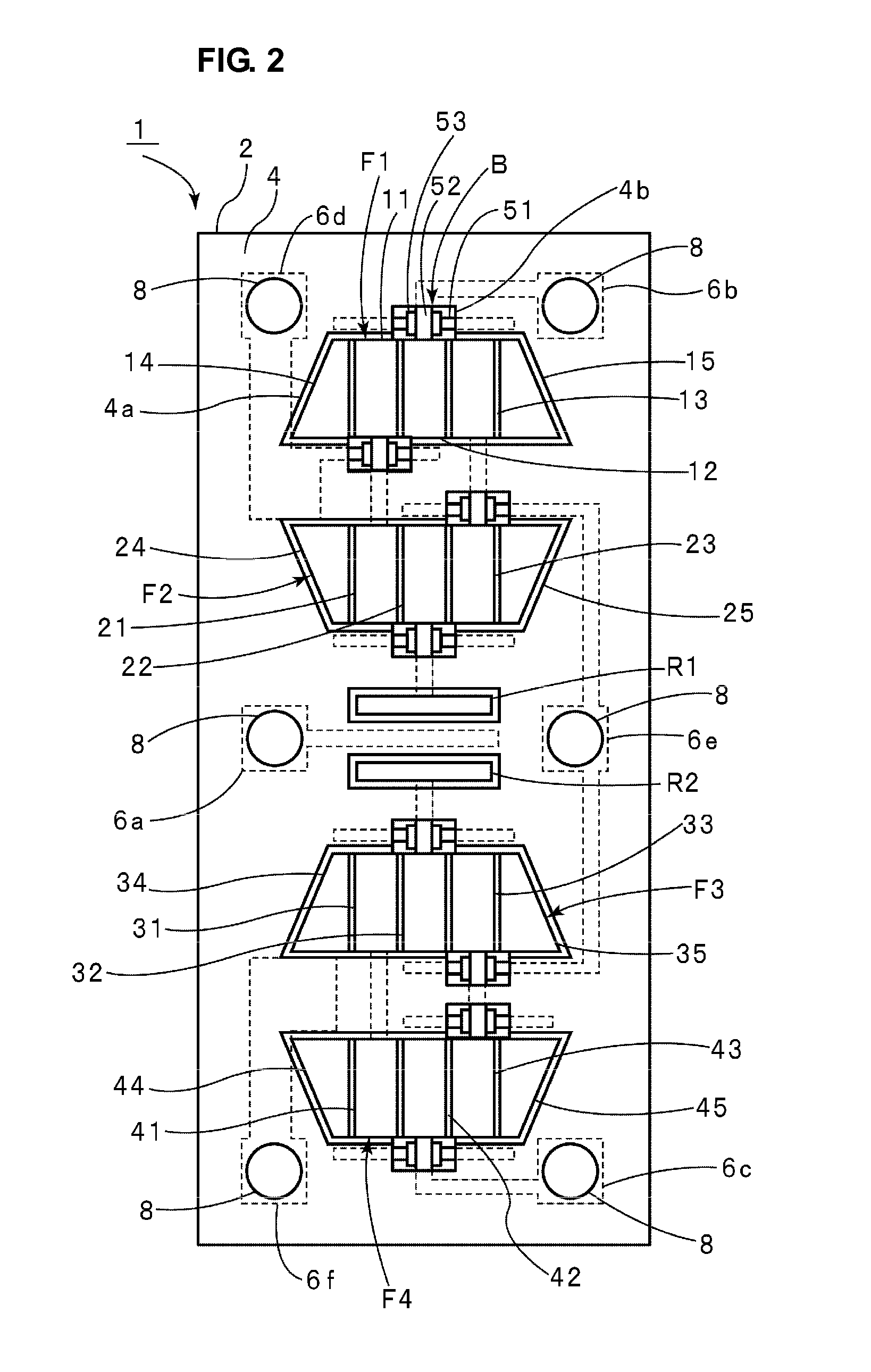
[0033]FIG. 1 is a schematic cross-section viewed from the front illustrating a surface acoustic wave device according to a preferred embodiment of the present invention, and FIG. 2 is a schematic plan view illustrating a state where a cover of the surface acoustic wave device is removed.

[0034]As shown in FIG. 1, a surface acoustic wave device 1 according to the present preferred embodiment includes a piezoelectric substrate 2. The piezoelectric substrate 2 is preferably composed of piezoelectric monocrystals such as LiTaO3, LiNbO3, or quartz crystal or piezoelectric ceramics. The piezoelectric substrate 2 includes an upper surface 2a serving as a first main surface and a lower surface 2b serving as a second main surface. Electrodes 3 including at least one IDT electrode are arranged on the upper surface 2a so as to excite surface acoustic waves. Spaces ...


PUM


Abstract

A highly reliable surface acoustic wave device includes wiring lines that do not easily rupture at a three-dimensional wiring portion. The surface acoustic wave device includes a plurality of surface acoustic wave elements located on a piezoelectric substrate, a supporting member arranged on the piezoelectric substrate so as to enclose vibrating portions including electrodes such as IDT electrodes, and a cover member stacked so as to cover openings of the supporting member and to define hollow spaces facing vibrating electrodes. Furthermore, a three-dimensional wiring portion at which a first wiring line and a second wiring line are stacked with an insulating layer interposed therebetween is provided on the piezoelectric substrate. The three-dimensional wiring portion is enclosed by the supporting member, and thereby disposed inside a space enclosed by the piezoelectric substrate, the supporting member, and the cover member.

Description

BACKGROUND OF THE INVENTION[0001]1. Field of the Invention[0002]The present invention relates to surface acoustic wave devices including a plurality of surface acoustic wave elements electrically connected to each other by wiring lines, and more specifically, relates to surface acoustic wave devices including three-dimensional wiring portions at which a plurality of wiring lines intersect with each other in a three-dimensional manner.[0003]2. Description of the Related Art[0004]To date, surface acoustic wave devices have been widely used for band-pass filters for, for example, cellular phones. In order to reduce the size of such surface acoustic wave devices, the following Japanese Unexamined Patent Application Publication No. 2006-217226 discloses a surface acoustic wave device shown in FIG. 7.[0005]A surface acoustic wave device 101 includes a piezoelectric substrate 102 composed of, for example, LiTaO3. An IDT electrode 103 is formed on the piezoelectric substrate 102. A protecti...

Claims


Application Information

Patent Timeline
Patent Type & Authority Applications(United States)
IPC IPC(8): H01L41/08H01L41/047
CPCH03H9/1092H03H9/059
Inventor OMOTE, RYOICHITAKADA, NORIHIKO
Owner MURATA MFG CO LTD
Why Eureka
Try Eureka