
Electric machine with non-coaxial rotors

a non-coaxial arrangement and electric machine technology, applied in the direction of motor/generator/converter stopper, dynamo-electric converter control, instruments, etc., can solve the problems of presenting limitations on the design of electric machines and undesirable coaxial arrangement of rotors

Inactive Publication Date: 2010-12-30
CASEY JOHN R
View PDF31 Cites 22 Cited by
  • Summary
  • Abstract
  • Description
  • Claims
  • Application Information

AI Technical Summary

Benefits of technology

[0009]It is envisioned that embodiments of the invention can be applied in a vehicle electric drive platform, and may provide advantages for performance, cost, and design considerations such as ground clearance, drive shaft angularity and body design. The electric machine with non-coaxial rotors may function as a combined motor / generator, an electromagnetic coupling between an engine and drive train of a vehicle, a differential drive between left and right wheels, or a differential drive between front and rear of a four-wheel drive vehicle. Embodiments of the invention may also find industrial application for differential drive of adjacent machine sections with non-coaxial drive axes.

Problems solved by technology

While functional, the prior design of electric machines to have rotors in a coaxial, side-by-side arrangement presents limitations on the design of the electric machine.
For example, arranging the rotors in a coaxial arrangement may be undesirable when incorporating the machine into an electric or hybrid vehicle where the amount of space may be limited.

Method used


Image

  • Electric machine with non-coaxial rotors
  • Electric machine with non-coaxial rotors
  • Electric machine with non-coaxial rotors

Examples


Embodiment Construction

[0029]The following descriptions describe various embodiments of electric machines having non-coaxial rotors. It is recognized that additional embodiments of such electric machines are also envisioned and that the scope of the invention is not to be limited by the embodiments described here below. For example, additional embodiments of the invention may include any number of rotors, at least two of which are non-coaxial, in any angular orientation with either intersecting or non-intersecting axes. In the following embodiments, design details of rotors, stators, bearings, gearing and electronic controls are not described, since these are well known in the state of the art.

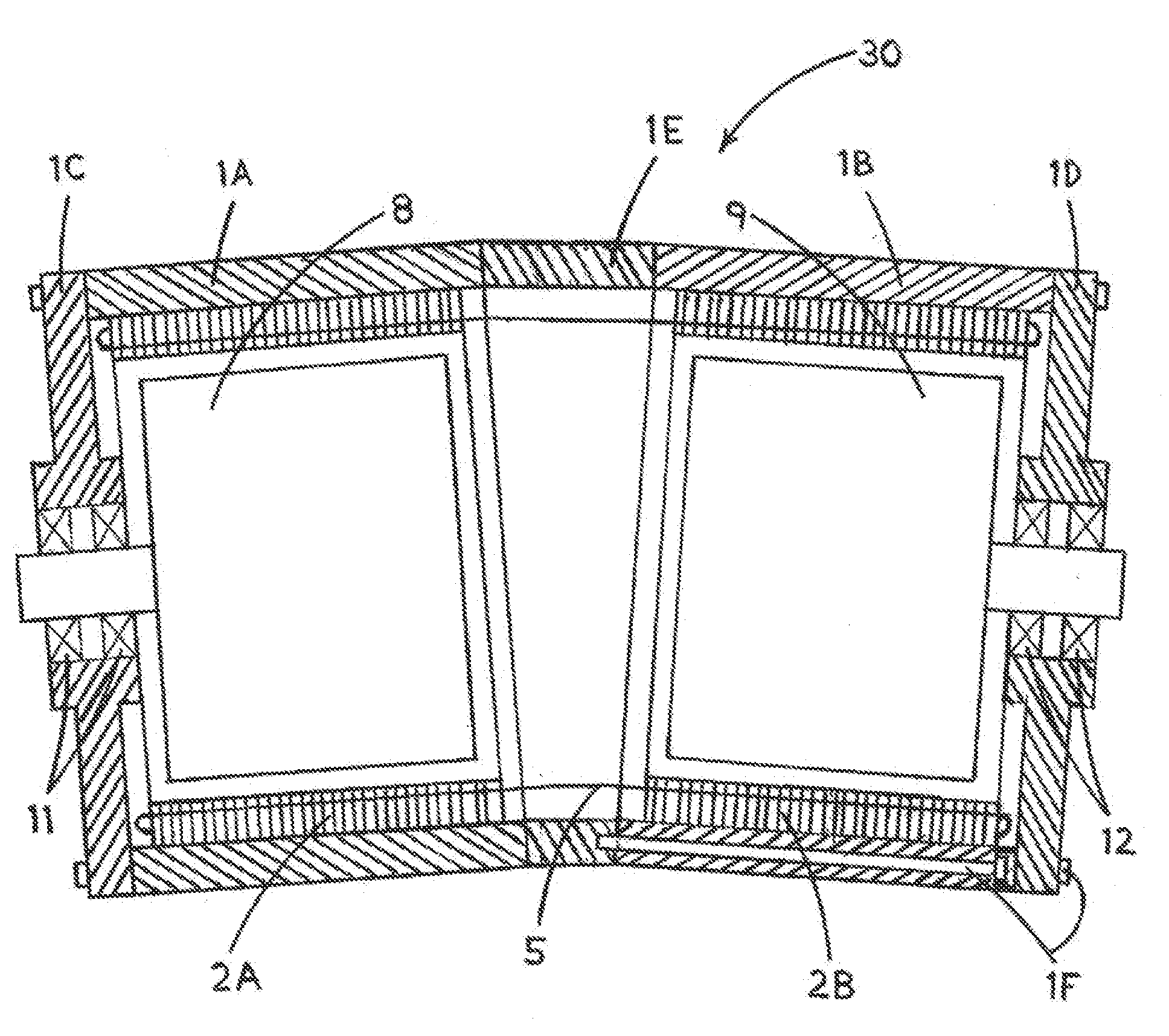
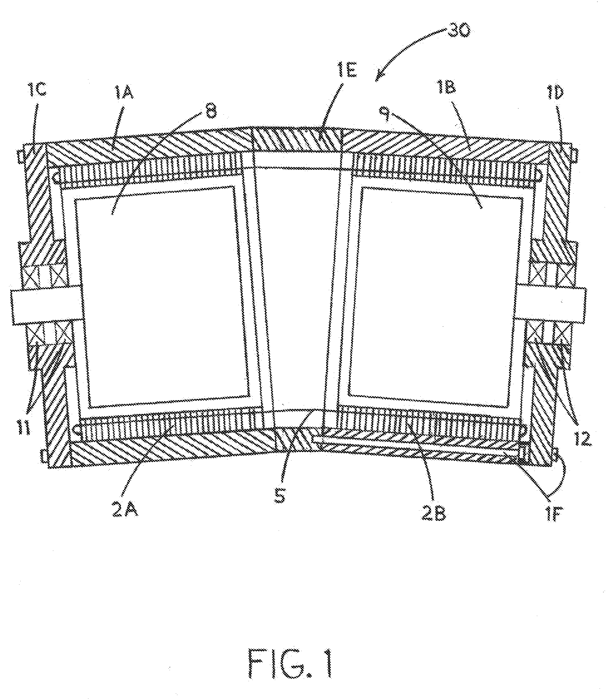
[0030]Referring now to FIG. 1, an electric machine configured as a radial flux machine 30 is shown having non-coaxial rotors which interact mutually with a shared set of stator windings according to an embodiment of the invention. The radial flux machine 30 includes a housing assembly 1 having two hollow body parts ...


PUM


Abstract

A rotary electric machine having plural rotary elements in a non-coaxial arrangement is disclosed. The rotary electric machine includes a housing assembly, at least one stator frame mounted in the housing assembly, at least one stator winding wound on the at least one stator frame, and at least two rotors mounted in the housing assembly having axes of rotation that are non-coaxial, wherein each of the at least two rotors is mechanically decoupled from the other rotors such that each of the at least two rotors rotates independent from one another. The rotary electric machine also includes a control unit, with the control unit including at least one electronic control electrically connected to the at least one stator winding. The control unit is configured to control an exchange of power to or from each of the at least one stator windings.

Description

BACKGROUND OF THE INVENTION[0001]Embodiments of the invention relate generally to rotary electric machines and, more particularly, to a rotary electric machine with plural rotary elements in a non-coaxial arrangement.[0002]Electric machines that function as motors and generators have been known in the art for many years. Electric motors range in size and output and operation. Electric motors use electric current or voltage as an input and then output rotation to a shaft member. Conversely, electric generators / alternators receive the rotation of a shaft as input and then output an electric current or voltage. The application of electric machines is widely varied and can be applied in industrial applications for differential drive of adjacent machine sections or can be applied in a vehicle electric drive platform as part of an electric or hybrid vehicle, for example.[0003]Certain electric machines have been developed that utilize multiple rotors and / or multiple stators, and various de...

Claims


Application Information

Patent Timeline
Patent Type & Authority Applications(United States)
IPC IPC(8): H02K16/02H02K11/00H02K7/116H02P31/00
CPCH02K16/00B60L15/2036Y02T10/7275Y02T10/641Y02T10/644Y02T10/72Y02T10/64
Inventor CASEY, JOHN R.
Owner CASEY JOHN R
Learn More