
SAR calculation for multichannel mr transmission systems

a multi-channel mr transmission system and sar calculation technology, applied in the direction of geological measurements, sensors, reradiation, etc., can solve the problems of global power loss and high complexity, and achieve the effect of accelerating calculation and efficien

Active Publication Date: 2010-12-30
SIEMENS HEATHCARE GMBH
View PDF10 Cites 21 Cited by
  • Summary
  • Abstract
  • Description
  • Claims
  • Application Information

AI Technical Summary

Benefits of technology

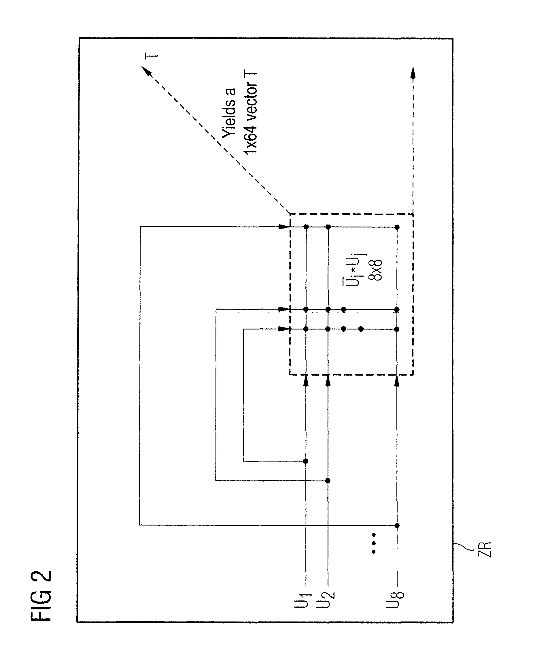
[0022]The method results in a look-ahead calculation for complete pulses and the sequences in which they are repeatedly sent: the cross-correlation matrix is summed for a complete transmission pulse and subsequently evaluated via multiplication with the sensitivity matrices. This enables an efficient, accelerated calculation.

Problems solved by technology

A high level of complexity exists if the local SAR should be comprehensively monitored or calculated in advance for parallel pulses (simultaneously emitted pulses).
However, because the local SAR is not directly measurable, it is necessary to rely on generating suitable body models representing the (complex) conductivity distribution and calculating in these models the fields that are produced by the respective array elements and the model points of the model.
The procedure seeks to combine adjacent model points with similar conductivities, but the problem remains that, due to the multiple overlaying possibilities of respective amplitudes and phases of the Nchannels (Nchannels can typically be 8), there is generally not a single “hotspot” in the body at which the electrical power density is always greatest.
An analogous problem is posed with regard to the global power loss if the total energy that is deposited in the patient volume is to be calculated from the time-dependent vector of the antenna voltages and a previously measured conductance matrix or, respectively, scatter matrix of the system.

Method used


Image

  • SAR calculation for multichannel mr transmission systems
  • SAR calculation for multichannel mr transmission systems
  • SAR calculation for multichannel mr transmission systems

Examples


Embodiment Construction

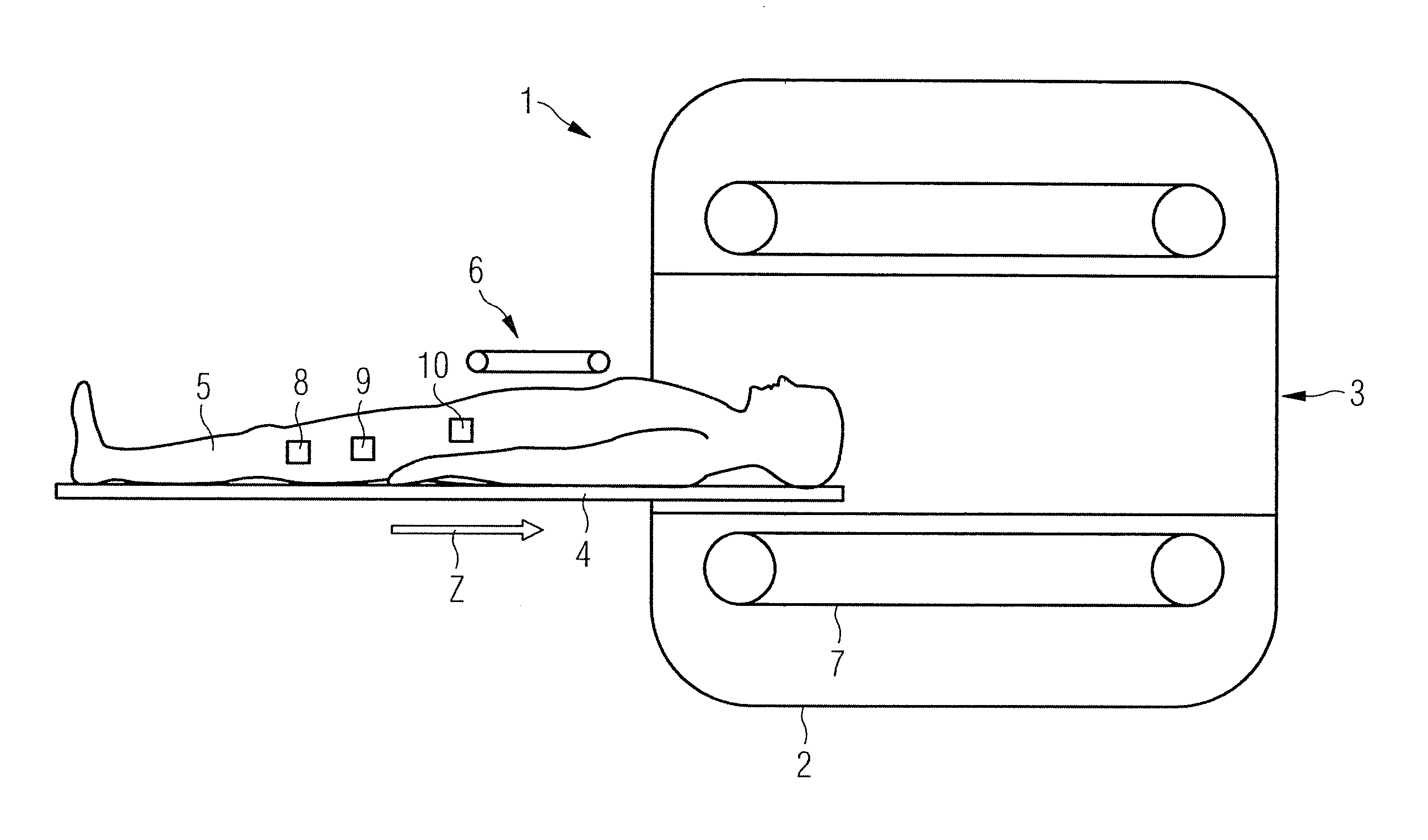
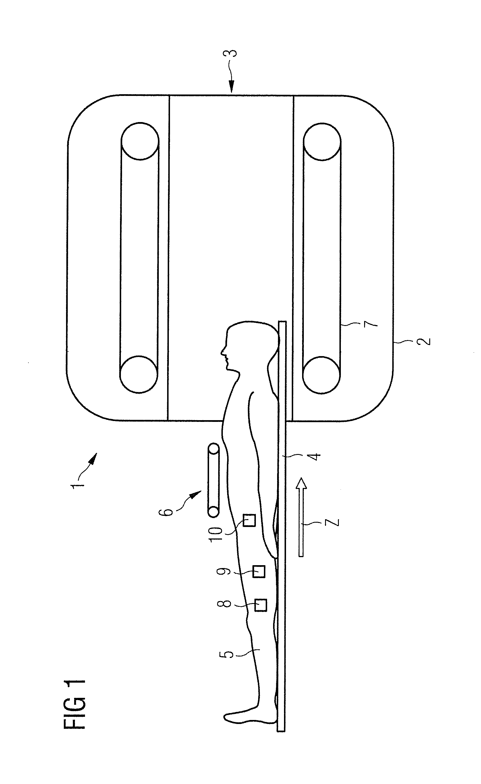
[0032]FIG. 1 shows a magnetic resonance apparatus (MRT) 1 with a whole-body coil 2 and a tube-shaped space 3 into which a patient bed 4 with an examination subject (for example a patient 5) and a local coil arrangement 6 can be driven in order to generate exposures of a subject 5 (for example a patient or a measurement dummy or another subject) that can be additionally processed afterward.

[0033]With regard to physical background:

[0034]In three-dimensional representation (for the coordinates x, y, z), an electrical field generated by N electrical transmission coils of at least one TX array can be represented as a vector with length 3*N, for example:

E=(E1X, E1Y, E1Z, E2X, E2Y, E2Z, . . . , ENX, ENY, ENZ).

[0035]A vector U of voltages (also called antenna element values in the following because they respectively cause a field strength caused by an antenna) respectively present at M (=Nchannels, for example eight) transmission coils is, for example,

U=(U1, . . . , UM)

[0036]A complex sensi...


PUM


Abstract

In a device and a method to determine SAR for a magnetic resonance tomography transmission system with multiple antenna elements, a single-column cross-correlation matrix of an antenna element matrix of antenna element values of multiple antenna elements of the magnetic resonance tomography transmission system is determined for each of multiple points in time or time periods. These single-column cross-correlation matrices are added into a sum cross-correlation matrix over a summation time period and the sum cross-correlation matrix is multiplied with a hotspot sensitivity matrix. The hotspot sensitivity matrix represents the sensitivities in at least one direction at a number of hotspot points in a subject located in the magnetic resonance tomography transmission system. The product of the sum cross-correlation matrix and the hotspot sensitivity matrix is multiplied with a value representing the dielectricity at least one hotspot point in order to determine a respective SAR value for hotspot points. If at least one SAR value exceeds a predetermined upper limit, the voltage applied to at least one antenna element or the current flowing in at least one antenna element is reduced or deactivated.

Description

BACKGROUND OF THE INVENTION[0001]1. Field of the Invention[0002]The invention concerns methods and devices for a SAR monitoring for a magnetic resonance tomography apparatus.[0003]2. Description of the Prior Art[0004]Magnetic resonance tomography apparatuses are known from DE 10 2005 052 564, for example.[0005]In the case of operation of MR scanners with a transmission (TX) array and with the generation of RF pulses that can exhibit an arbitrary pulse shape for each array element (variation of amplitude and phase), a multitude of possibilities results for overlaying the electrical fields in the body of the examination subject. A high level of complexity exists if the local SAR should be comprehensively monitored or calculated in advance for parallel pulses (simultaneously emitted pulses). Monitoring of the local SAR value, however, is absolutely necessary for the safety of the patient and is required by corresponding regulations. The overlaying of the electrical fields in array ante...

Claims


Application Information

Patent Timeline
IPC IPC(8): G01R33/44
CPCG01R33/288G01R33/5612G01R33/3415
Inventor GEBHARDT, MATTHIASVESTER, MARKUS
Owner SIEMENS HEATHCARE GMBH
Learn More