
Tire condition acquisition device and tire condition monitoring system

Active Publication Date: 2010-12-30
YOKOHAMA RUBBER CO LTD
View PDF11 Cites 20 Cited by
  • Summary
  • Abstract
  • Description
  • Claims
  • Application Information

AI Technical Summary

Benefits of technology

[0015]The present invention provides an advantage in that a liquid of a tire repair agent will not easily plug a ventilation hole even if a tire puncture is repaired using a tire puncture repair agent. Therefore malfunction and loss of function of a tire condition acquisition device can be reduced compared to conventional technologies.

Problems solved by technology

Conventionally, tire air pressure inspection management for vehicles has been important, and many accidents are caused by improper tire pressure.
However, if the tire equipped with the tire information acquisition device is punctured and the tire is repaired using a tire puncture repair agent, there is a problem that the tire information acquisition device will cease functioning due to the tire puncture repair agent.
Specifically, if the tire puncture repair agent adheres to the ventilation hole of the tire information acquisition device, communication between the tire inner space and the air pressure sensor will be blocked, thereby making detection of the air pressure impossible.
However, with the tire air pressure monitoring system described in Japanese Unexamined Patent Application Publication No. 2007-196834, puncture determining means and tire puncture repair agent use determining means are required, resulting in a complex construction, and increased manufacturing costs.
Additionally, since a warning is issued after repairs are made using the tire puncture repair agent, even if the tire air pressure value is at a normal value, there is a problem that a driver will have difficulty determining whether or not the tire air pressure is normal.
Furthermore, with the wheel condition detecting device described in Japanese Unexamined Patent Application Publication No. 2008-062730, the connecting part opening and closing mechanism is complicated.
Therefore, there are problems of complicated manufacturing and additional costs.

Method used


Image

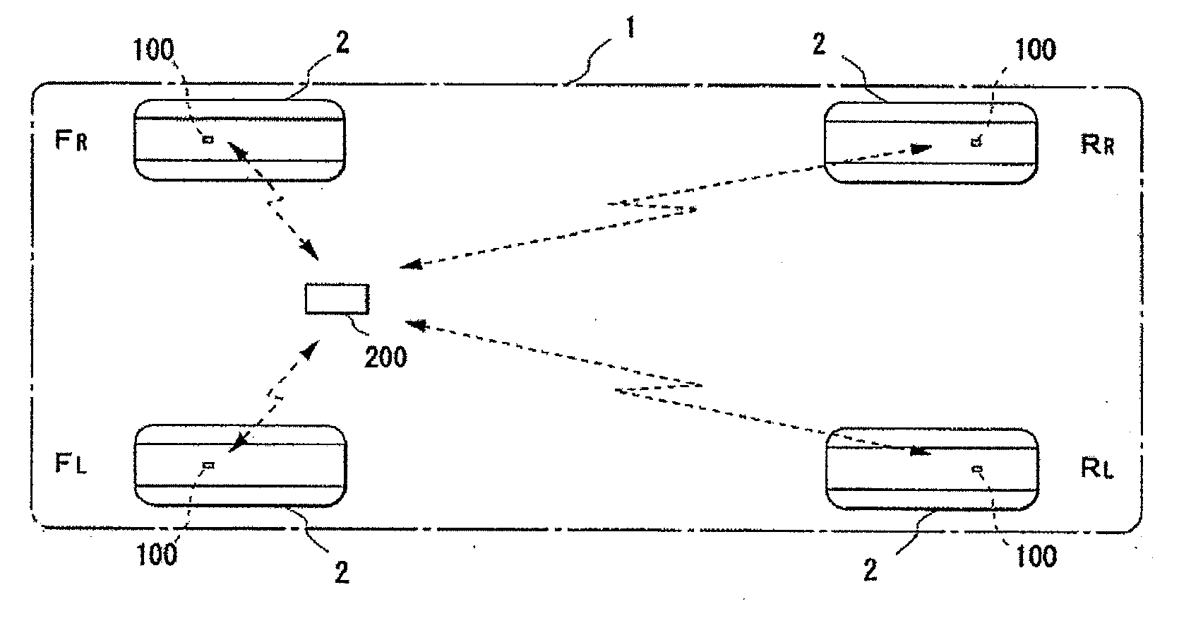
  • Tire condition acquisition device and tire condition monitoring system
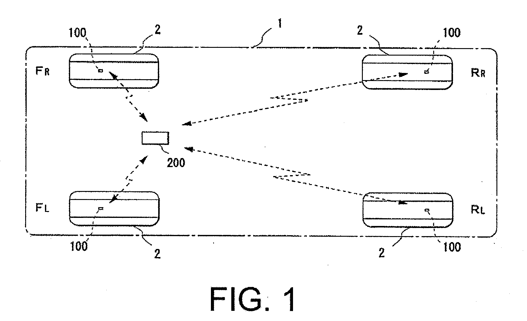
  • Tire condition acquisition device and tire condition monitoring system
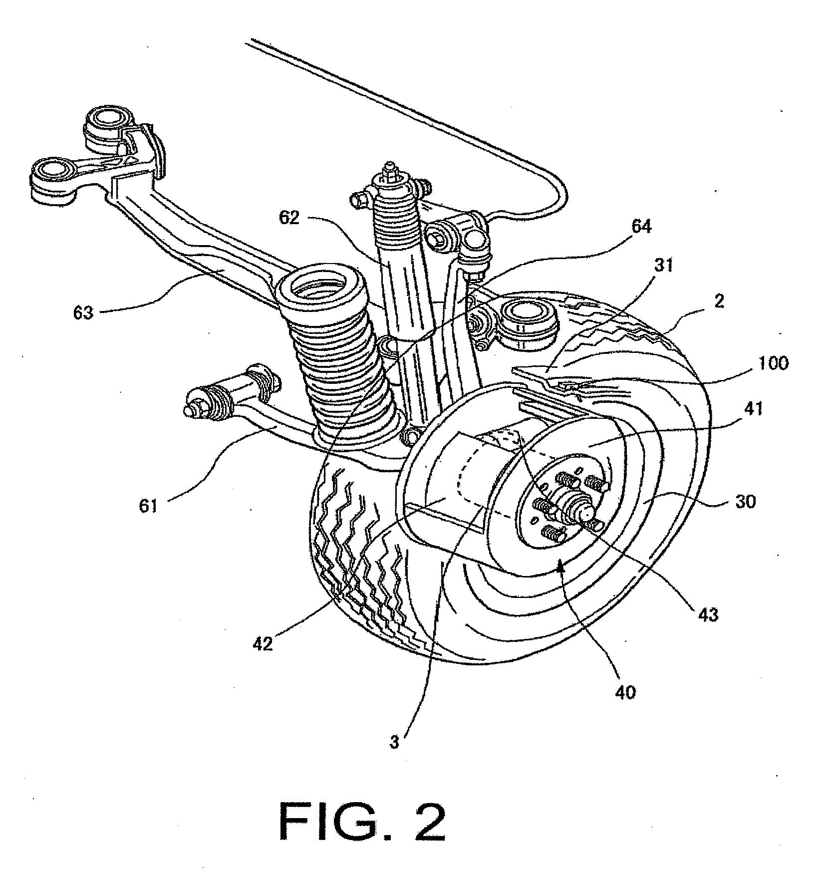
  • Tire condition acquisition device and tire condition monitoring system

Examples


example 1

[0068]With the tire condition acquisition device 100 of Example 1, as illustrated in FIG. 4, when the housing of the tire condition acquisition device 100 is mounted on the rim 31 in the tire 2, the ventilation hole 101 is provided so as to open to a side in a direction that centrifugal force due to rotation of the tire 2 acts. In addition, a diameter of the ventilation hole 101 is set to be 0.5 mm or less.

[0069]By providing the ventilation hole 101 on the side in the direction that centrifugal force acts, the puncture repair liquid will not easily enter the ventilation hole 101. Additionally, the puncture repair liquid will not easily enter the ventilation hole 101 due to surface tension because the diameter of the ventilation hole 101 is 0.5 mm or less. Therefore, malfunction and function loss of the tire condition acquisition device 100 can be reduced, as compared to conventional technologies.

example 2

[0070]With the tire condition acquisition device 100 of Example 2, as illustrated in FIG. 9 and FIG. 10, a shielding member 300 having both water repellency and breathability is applied so as to cover the ventilation hole 101. By blocking the ventilation hole 101 with the shielding member 300 that has been treated so as to be water repellent, the puncture repair liquid will not easily enter the ventilation hole 101. Therefore, malfunction and function loss of the tire condition acquisition device 100 can be reduced, as compared to conventional technologies.

[0071]Note that the shielding member 300 must be a member with breathability, and may be a breathable member permeated with a water repellent agent, or may be a cloth with ultrafine raised hairs.

[0072]Furthermore, even if a nonwoven material, a woven material, or a sponge with a breathable foam is used as the shielding member 300, the puncture repair liquid will likewise not easily enter into the ventilation hole 101.

[0073]Further...

example 3

[0074]In Example 3, the housing of the tire condition acquisition device 100 is formed from a member having water repellency. By constructing the housing of the tire condition acquisition device 100 using the member having water repellency, the puncture repair liquid will not easily enter the ventilation hole 101. Therefore, malfunction and loss of function of the tire condition acquisition device 100 can be reduced, as compared to conventional technologies.

[0075]Note that the material with water repellency from which the member that forms the housing of the tire condition acquisition device 100 is constructed can be, for example, a silicon resin or a fluorine resin; a modified resin grafted with an organic silyl group or a fluoroalkyl group, or the like; or the like. Furthermore, as with the shielding member of Example 2, the member surface is preferably constructed from a material having a water contact angle of 80 degrees or larger. Additionally, an inner surface of the ventilati...


PUM


Abstract

A tire condition acquisition device located in a tire and that transmits at least tire internal air pressure information includes: a housing that allows outside air to enter in only through a ventilation hole; an air pressure detecting element disposed in the housing and that detects an air pressure of air that enters in through the ventilation hole, and converts the detected air pressure to an electric signal which is then output; and a transmission circuit disposed in the housing and that transmits the detected air pressure information via electromagnetic waves based on the electric signal output from the air pressure detecting element; wherein at least the ventilation hole and an area peripheral thereto are treated so as to be water repellent.

Description

PRIORITY CLAIM[0001]This application is based upon and claims the benefit of priority from Japanese Patent Application No. 2009-152241, filed Jun. 26, 2009, the entire contents of which is incorporated herein by reference.BACKGROUND[0002]1. Technical Field[0003]The present invention relates to a tire condition acquisition device and tire condition monitoring system that can avoid malfunction and function loss due to a tire puncture repair agent.[0004]2. Related Art[0005]Conventionally, tire air pressure inspection management for vehicles has been important, and many accidents are caused by improper tire pressure. Therefore, tire condition monitoring systems are known that include a tire information acquisition device in each wheel that detects and transmits information regarding an air pressure in a wheel tire, and a monitoring device that acquires the tire air pressure information transmitted from the tire information acquisition devices in each tire, monitors the air pressure for ...

Claims


Application Information

Patent Timeline
IPC IPC(8): B60C23/00
CPCB60C23/0494B60C23/0408
Inventor KANENARI, DAISUKE
Owner YOKOHAMA RUBBER CO LTD
Learn More