Corrugated Leaching Chamber with Hollow Pillar Supports

a leaching chamber and hollow pillar technology, applied in the direction of sewage draining, sewer systems, construction, etc., can solve the problems of increasing stacking height and not enabling horizontal pivoting, so as to increase the strength, and increase the amount of storage area and leaching area.

Active Publication Date: 2010-12-30
INFILTRATOR WATER TECH LLC
View PDF30 Cites 11 Cited by
  • Summary
  • Abstract
  • Description
  • Claims
  • Application Information

AI Technical Summary

Benefits of technology

[0018]The unique corrugation width relationships enable more corrugations per unit length which increases strength, and they increase the amount of storage area and leaching area per unit length of chamber, compared to comparable chambers which have corrugations. Chambers having pillars and or the specially proportioned corrugation widths may have closed ends or open ends, with and without connectors for mating with other chambers. The corrugation width features may be used with or without pillars. The pillar features may be used in chambers without the corrugation width features.
[0019]In another aspect of the invention, when a group of chambers comprises a family which has different profiles and or different widths, each chamber in the group has a common-size end connector. Thus, a string of mixed size chambers can be created. And the number of accessories, such as end caps and couplers, which an installer has to carry in inventory, is reduced.
[0020]Exemplary chambers in accord with the invention are able to meet industry performance standards. They are strong, economically made, and economically transported and stored due to good stacking characteristics. Exemplary chambers have a combination of low profile and good strength, together with high storage volume, low plastic weight and high leaching area, all per unit length of chamber. Exemplary chambers may be made by different plastic forming means.

Problems solved by technology

In alternative chamber embodiments, the connectors overlap-underlap but do not enable pivoting in the horizontal plane.
Among other reasons, such ribs may increase stacking height.

Method used


Image

  • Corrugated Leaching Chamber with Hollow Pillar Supports
  • Corrugated Leaching Chamber with Hollow Pillar Supports
  • Corrugated Leaching Chamber with Hollow Pillar Supports

Examples


Embodiment Construction

[0047]This application is related to U.S. provisional application No. 61 / 269,880, filed Jun. 29, 2009, and No. 61 / 396,524, filed May 28, 2010, the disclosures of which are incorporated herein by reference in their entireties.

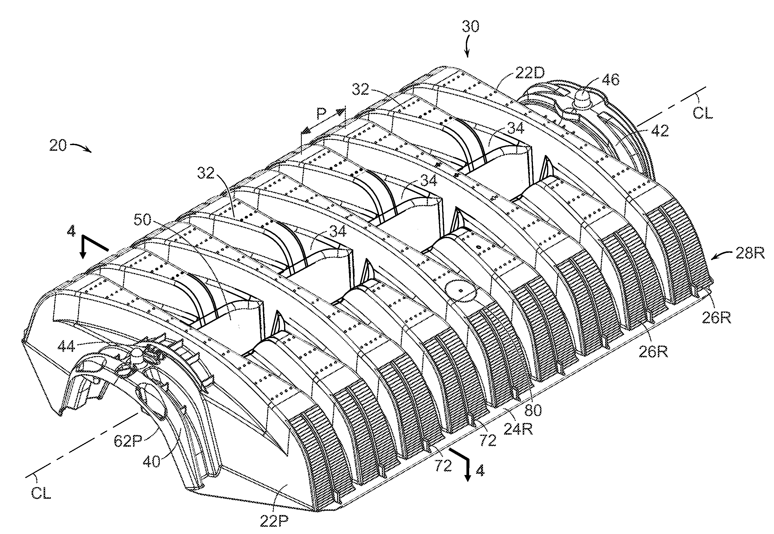
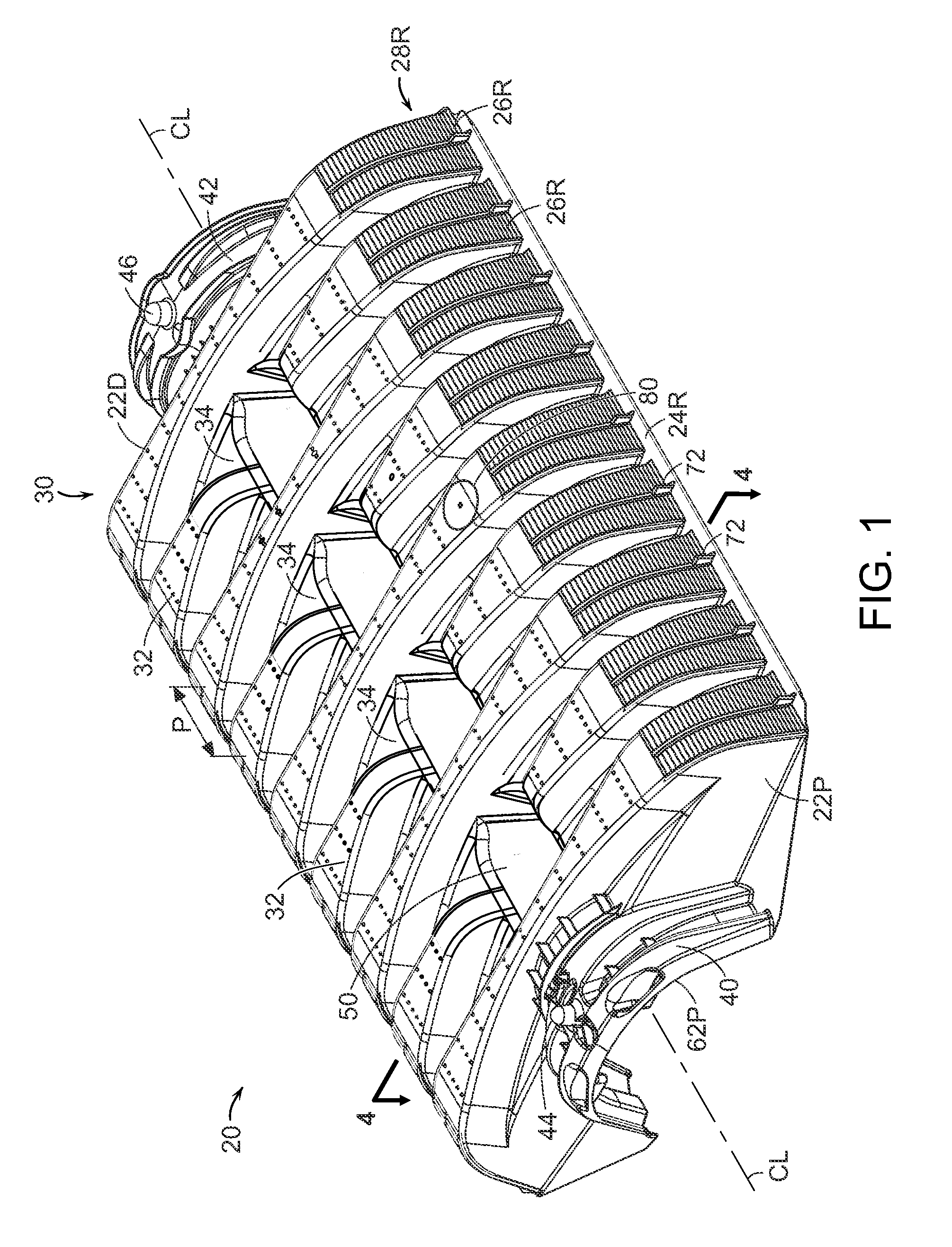
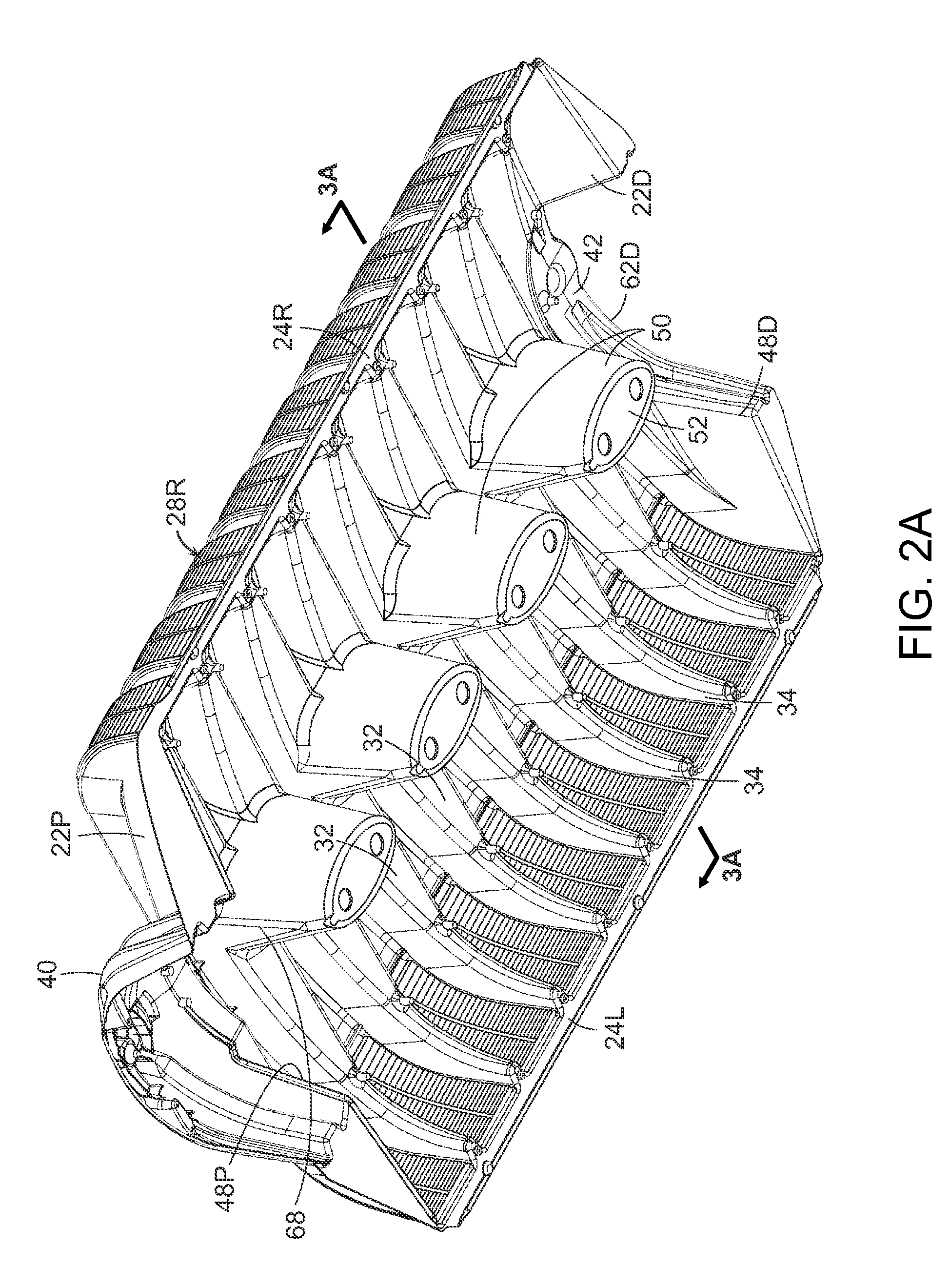
[0048]The present invention is described in terms of a thermoplastic leaching chamber. FIGS. 1 and 2A show an injection molded thermoplastic chamber 20 in oblique view, respectively looking down on the top of the chamber and up at the bottom of the chamber. FIG. 3A is a simplified transverse vertical plane projected cross section of the chamber, through one of the center pillars. An exemplary chamber 20 may have a base width W of about 34 inches and a height H of about eight inches. The length L of the chamber is nominally 48 inches. The actual overall length is about 52 inches, so that when chambers are overlapped by means of their end connectors, each chamber contributes about 48 inches to the length of a string of chambers. The foregoing shorter dimension, i....


PUM


Abstract

A plastic leaching chamber has an arch shape cross section, corrugations, and one or more hollow pillars extending downwardly within the interior of the chamber, to support the top of the chamber when the chamber is under load during use. Chambers nest within one another to form a stack of chambers for transport or storage. Chambers have peak corrugations which are substantially wider than the intervening valley corrugations. Chambers having different widths and profiles have common size connectors.

Description

CROSS-REFERENCE TO RELATED APPLICATIONS[0001]This application claims the benefit under 35 U.S.C. §119(e) of U.S. provisional application No. 61 / 396,524, filed May 28, 2010, and U.S. provisional application No. 61 / 269,880, filed Jun. 29, 2009, the disclosures of which are incorporated herein by reference in their entireties.TECHNICAL FIELD[0002]The present invention relates to apparatus for collecting, receiving, detaining or dispersing liquids when buried, in particular, to leaching chambers for receiving and dispersing wastewater.BACKGROUND[0003]As described in a number of patents and other publications, a familiar commercial leaching chamber is made of injection molded thermoplastic, has an arch shape cross section, an open bottom, a multiplicity of corrugations, and perforated sidewalls. Such chambers are buried in soil to receive wastewater, typically from a septic tank. An exemplary current commercial chamber is an Infiltrator® Quick4® chamber sold by Infiltrator Systems, Inc.,...

Claims


Application Information

Patent Timeline
Patent Type & Authority Applications(United States)
IPC IPC(8): E02B11/00
CPCE03F1/003
Inventor MOORE, JR., ROYCOPPES, BRYAN A.HALLAHAN, DENNIS F.CARDILLO, CHRISTOPHER R.
Owner INFILTRATOR WATER TECH LLC
Why Eureka
Try Eureka