Stator Device, Motor Constructed Thereby, and Heat-Dissipating Fan Including The Stator Device

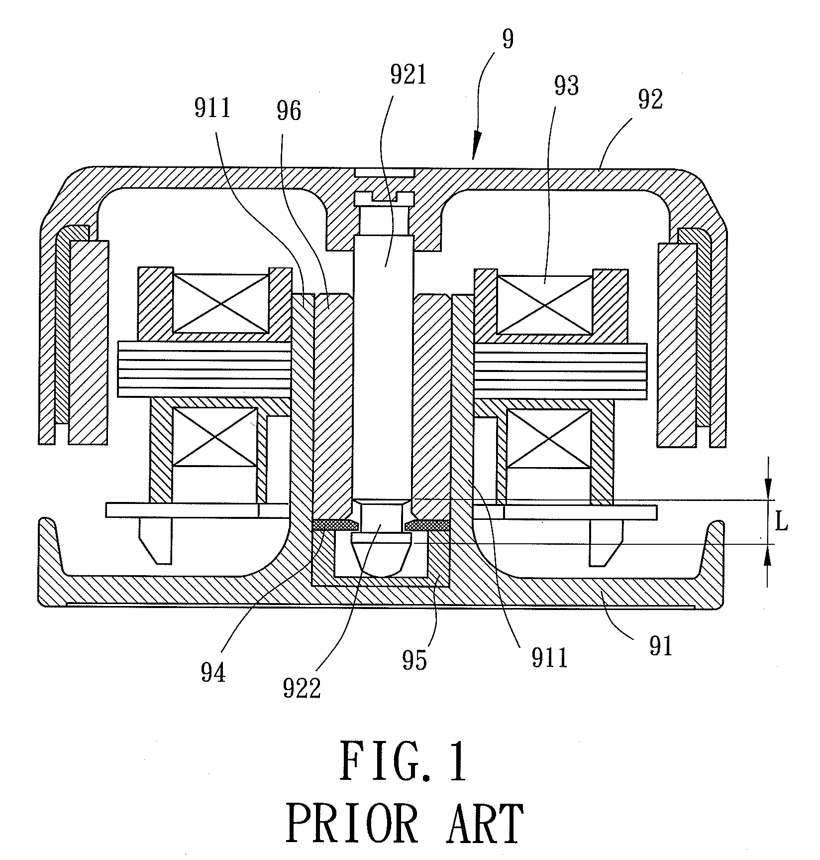
a stator device and motor technology, applied in the direction of positive displacement liquid engines, liquid fuel engines, piston pumps, etc., can solve the problems of inconvenient assembly, inability to enhance the rotational stability of the rotor 92, and inability to achieve the quality control of the assembly of the motor. , to achieve the effect of preventing disengagemen

Active Publication Date: 2010-12-30
SUNONWEALTH ELECTRIC MACHINE IND
View PDF9 Cites 24 Cited by
  • Summary
  • Abstract
  • Description
  • Claims
  • Application Information

AI Technical Summary

Benefits of technology

[0006]An objective of the present invention is to provide a stator device including a stator unit having a limiting member extending through a groove in

Problems solved by technology

The rotational stability of the rotor 92 can not be enhanced, which is a problem for a miniature motor.
Namel

Method used


Image

  • Stator Device, Motor Constructed Thereby, and Heat-Dissipating Fan Including The Stator Device
  • Stator Device, Motor Constructed Thereby, and Heat-Dissipating Fan Including The Stator Device
  • Stator Device, Motor Constructed Thereby, and Heat-Dissipating Fan Including The Stator Device

Examples


Embodiment Construction

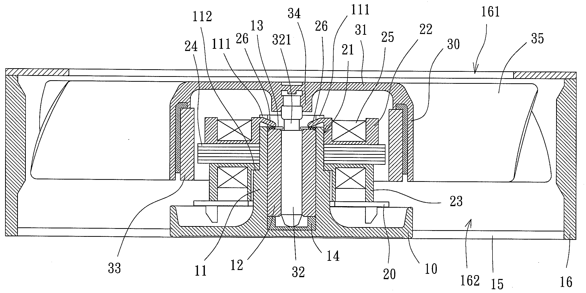
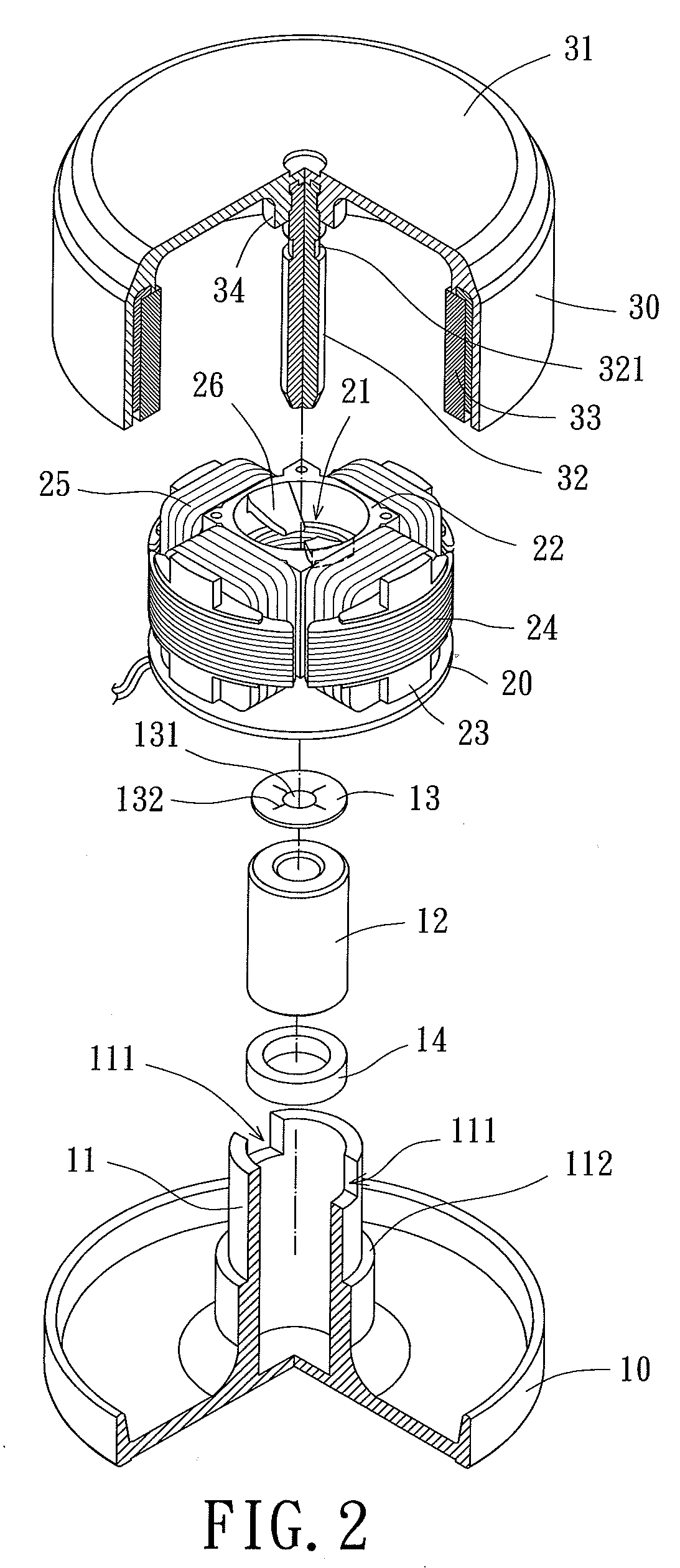
[0027]A motor of a first embodiment according to the preferred teachings of the present invention is shown in FIGS. 2-4 of the drawings. The motor includes a stator device and a rotor 30 rotatably mounted to the stator device about an axis. The stator device includes a base 10 and a stator unit 20. The base 10 includes a shaft tube 11 in a center thereof. Preferably, the shaft tube 11 has a closed bottom end. The shaft tube 11 receives a bearing 12, an abutting plate 13 and a support 14 serving as a reservoir for receiving lubricant. The shaft tube 11 further includes a top end having two grooves 111 in the form of two notches in a top face of the shaft tube 11. Each groove 111 includes a width in a horizontal direction perpendicular to the axis. However, shaft tube 11 can include only one groove 111 or more than two grooves 111 according to the teachings of the present invention. An outer periphery of the shaft tube 11 includes a positioning section 112 shown as a shoulder formed b...


PUM


Abstract

A stator device includes a base having a shaft tube receiving a bearing. The shaft tube includes a top end having at least one groove. A stator unit is mounted around an outer periphery of the shaft tube. The stator unit includes at least one limiting member extending through the at least one groove into the shaft tube. The at least one limiting member prevents the bearing from disengaging from the shaft tube, enhancing assembling convenience. The stator can be coupled with a rotor to form a motor with enhanced assembling convenience and enhanced rotational stability. The base can be interconnected by connecting members to a housing having air inlet and outlet sides. Vanes can be formed on the hub of the rotor to form an impeller. Thus, a heat-dissipating fan can be formed from the stator device.

Description

BACKGROUND OF THE INVENTION[0001]1. Field of the Invention[0002]The present invention relates to a stator device and, more particularly, to a stator device allowing easy assembly. The present invention also relates to a motor including the stator device. The present invention also relates to a heat-dissipating fan including the stator device.[0003]2. Description of the Related Art[0004]FIG. 1 shows a conventional motor 9 including a base 91, a rotor 92, and a stator unit 93. The base 91 includes a shaft tube 911 receiving a bearing 96, a retainer ring 94, and a support 95 serving as a reservoir for receiving lubricant. The rotor 92 includes a shaft 921 rotatably extending through the bearing 96. The retainer ring 94 is engaged in an annular groove 922 formed in an outer periphery of the shaft 921 and adjacent a distal end of the shaft 921 rotatably supported by the support 95. The stator unit 93 is mounted around the shaft tube 911 for driving the rotor 92 to rotate.[0005]However, l...

Claims


Application Information

Patent Timeline
IPC IPC(8): F04D25/08H02K5/167
CPCF04D29/056H02K5/1675H02K1/187F04D29/646
Inventor HORNG, ALEX
Owner SUNONWEALTH ELECTRIC MACHINE IND
Why Eureka
Try Eureka