Superhydrophobic surfaces for drag reduction

a technology of superhydrophobic surfaces and drag reduction, applied in the direction of electrical equipment, chemistry apparatus and processes, thin material processing, etc., can solve the problem of too expensive implementation, and achieve the effect of reducing the drag for

Inactive Publication Date: 2010-12-30
UNIV OF MASSACHUSETTS
View PDF4 Cites 33 Cited by
  • Summary
  • Abstract
  • Description
  • Claims
  • Application Information

AI Technical Summary

Benefits of technology

[0022]In one embodiment, the engineered structure further comprises at least one aperture defined within the surface of the solid object, and a source of pressurized gas configured to provide the gas to the volume defined by the at least two breaker posts and the plurality of posts. In one embodiment, the engineered structure further comprises pressure monitoring device configured to measure a pressure of the gas. In one embodiment, the engineered structure further comprises a pressure control device configured to control a pressure of the gas.
[0023]In yet another aspect, the invention provides a method of manufacturing an engineered structure configured to provide reduced drag force experienced by a solid object and a fluid having relative motion therebetween. The method comprises the steps of providing a solid object having a surface; proving on the surface of the solid object a plurality of parallel ridges ex

Problems solved by technology

All of these techniques have drawbacks from being too expensive to implement or having a narrow range of Reynolds numbers (flow speeds) over which they are viable.
While the general principles that control the supe

Method used


Image

  • Superhydrophobic surfaces for drag reduction
  • Superhydrophobic surfaces for drag reduction
  • Superhydrophobic surfaces for drag reduction

Examples


Embodiment Construction

[0054]We have recently demonstrated that superhydrophobic surfaces can be used as a new passive technique for reducing drag over a wide range of Reynolds numbers from laminar (see Ou, J., Perot, J. B., and Rothstein, J. P., Phys. Fluids, 16 (2004) 4635-4660; Joseph, P., Cottin-Bizonne, C., Benoit, J.-M., Ybert, C., Journet, C., Tabeling, P., and Bocquet, L., Phys. Rev. Lett., 97 (2006) 156104) to turbulent flows (see Martell, M. B., Perot, J. B., and Rothstein, J. P., J. Fluid Mech., 620 (2009) 31-41; Daniello, R., Waterhouse, N. E., and Rothstein, J. P., Submitted to Phys. Fluids, (2009), unpublished).

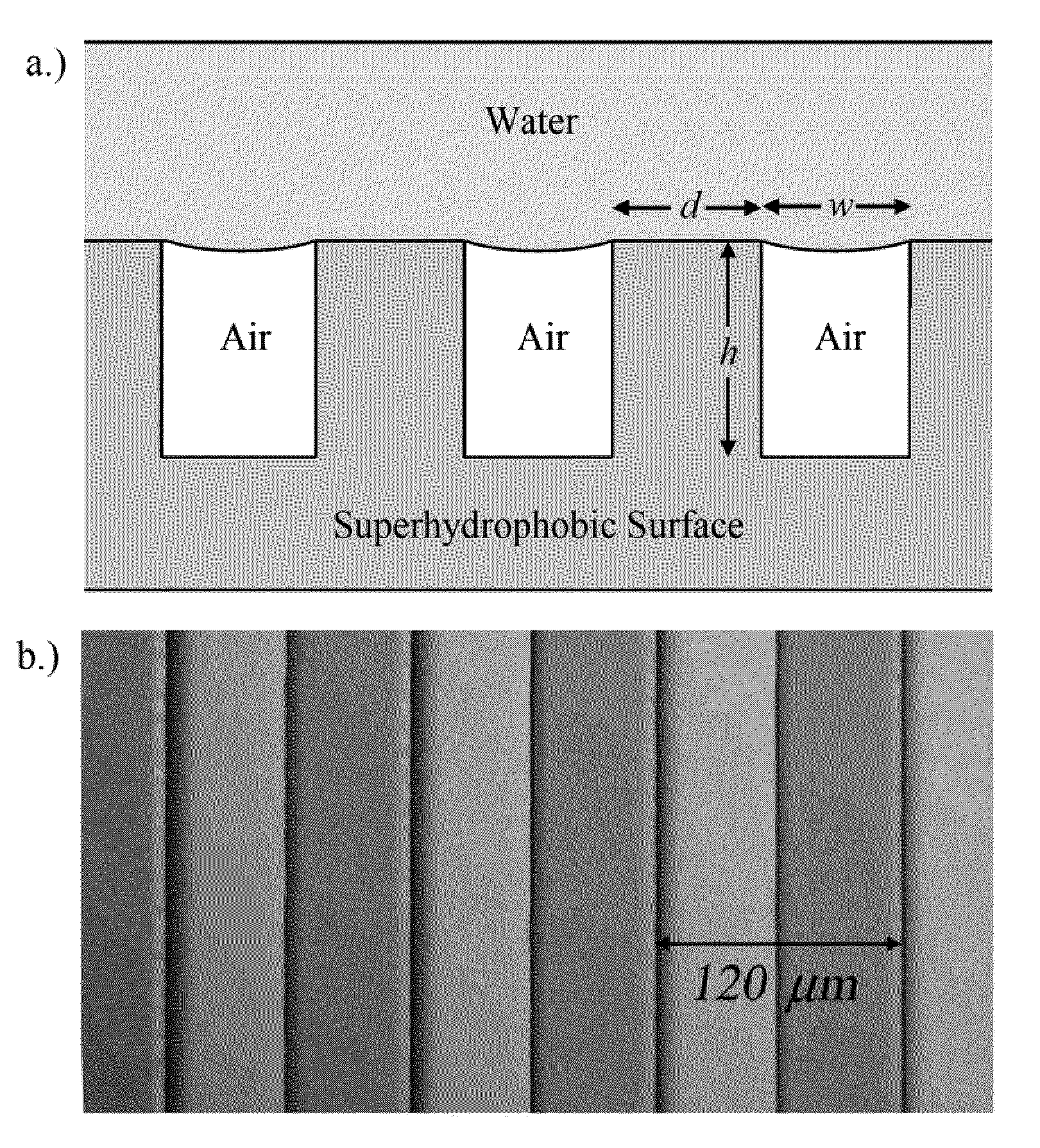
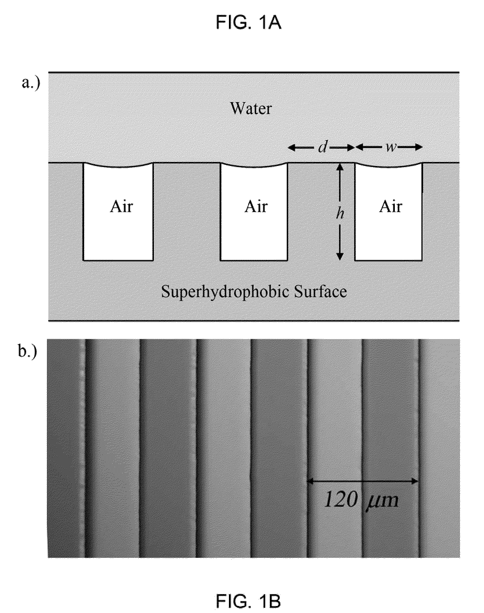
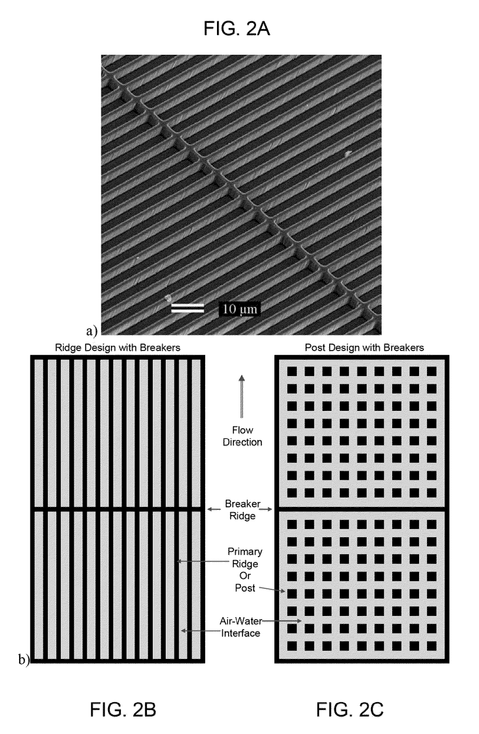
[0055]We demonstrate that periodic, micropatterned superhydrophobic surfaces, previously noted for their ability to provide laminar flow drag reduction, are capable of reducing drag in the turbulent flow regime. Superhydrophobic surfaces contain micro or nanoscale hydrophobic features which can support a shear-free air-water interface between peaks in the surface topology. Particle im...


PUM

PropertyMeasurementUnit
Forceaaaaaaaaaa
Pressureaaaaaaaaaa
Volumeaaaaaaaaaa

Abstract

Superhydrophobic surfaces according to the invention contain micro or nanoscale hydrophobic features which can support a shear-free air-water interface between peaks in the surface topology. The surface of an engineered structure is patterned with a plurality of parallel ridges extending from the surface. The ridges have a width d and a height h, and are spaced apart by a first spacing dimension w. The ridges extend along the surface of the solid object for a predefined length l. Breaker ridges are situated between the parallel ridges, and are oriented at an angle to the parallel ridges. The breaker ridges are preferably spaced apart by a second spacing dimension. The breaker ridges and the parallel ridges are configured to define a volume wherein a gas may be situated. The engineered structure is configured to provide a reduced drag force between itself and a fluid.

Description

CROSS-REFERENCE TO RELATED APPLICATIONS[0001]This application claims priority to and the benefit of co-pending U.S. provisional patent application Ser. No. 61 / 177,453, filed May 12, 2009, which application is incorporated herein by reference in its entirety.STATEMENT REGARDING FEDERALLY FUNDED RESEARCH OR DEVELOPMENT[0002]The U.S. Government has certain rights in this invention pursuant to Grant No. N00014-06-1-0497 awarded by Office of Naval Research.FIELD OF THE INVENTION[0003]The invention relates to hydrodynamic flow systems in general and particularly to surfaces that are constructed to provide reduced hydrodynamic drag.BACKGROUND OF THE INVENTION[0004]The development of technologies which produce significant drag reduction in turbulent flows can have a profound effect on a variety of existing technologies. Drag reduction in turbulent flows can be achieved through a number of different mechanisms including the addition of polymers to the fluid (see Virk, P. S., AIChE J., 21 (19...

Claims


Application Information

Patent Timeline
IPC IPC(8): B32B3/30B32B37/00
CPCF15D1/10Y10T156/1089Y10T428/2457
Inventor ROTHSTEIN, JONATHAN P.DANIELLO, ROBERT
Owner UNIV OF MASSACHUSETTS
Why Eureka
Try Eureka