Electrical push-pull plug connector

a plug connector and push-pull technology, applied in the direction of coupling device connection, coupling/disengagement of coupling parts, electric apparatus, etc., can solve the problem of relatively simple locking mechanism of the proposed electrical push-pull plug connector, and achieve the effect of simple manufacturing and easy assembly

Inactive Publication Date: 2010-12-30
CONINVERS
View PDF14 Cites 10 Cited by
  • Summary
  • Abstract
  • Description
  • Claims
  • Application Information

AI Technical Summary

Benefits of technology

[0009]Therefore, the invention intends to solve these problems by proposing an improved plug connector of this type wherein the plug component is easy to plug into and pull out of the matching plug component and, when fully inserted in the matching plug component, is held securely in the matching plug component even under high vibration loads. In addition, the locking mechanism of the proposed electrical push-pull plug connector is relatively uncomplicated and consists of few parts that are simple to manufacture, easy to assemble, and inexpensive.

Problems solved by technology

In addition, the locking mechanism of the proposed electrical push-pull plug connector is relatively uncomplicated and consists of few parts that are simple to manufacture, easy to assemble, and inexpensive.

Method used


Image

  • Electrical push-pull plug connector
  • Electrical push-pull plug connector
  • Electrical push-pull plug connector

Examples


Embodiment Construction

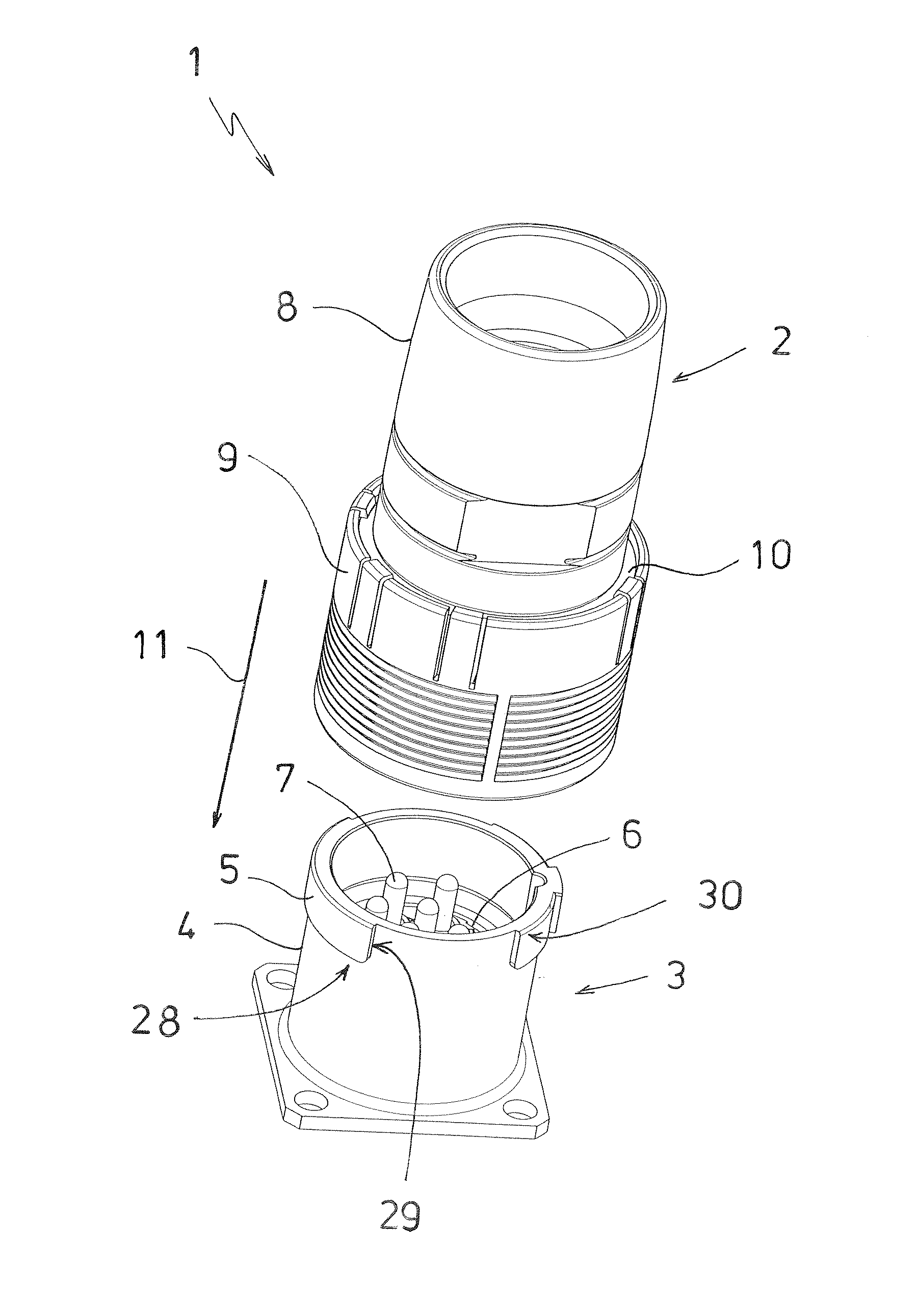
[0032]FIG. 1 shows a perspective view of an electrical plug connector 1 according to the invention designed as a round plug connector. The plug connector 1 comprises a plug component 2 arranged at the end of a cable (not shown) and a matching plug component 3 that is intended to be attached to a device housing (also not shown). The matching plug component 3 comprises a cylindrical plug-in area 4 with a segmented collar 5 that encloses a contact carrier 6 with electrical contacts 7. The plug component 2 has an essentially cylindrical plug component housing 8 that carries a tubular sliding sleeve 9 on the plug-in side facing the matching plug component 3. The sliding sleeve 9 overlaps a—in the plug-in direction—frontal circumferential wall area 10 of the plug component housing 8 which, in turn, overlaps on the outside the plug-in area 4 with the collar 5 when the plug component 2 is connected to the matching plug component 3, as shown in FIG. 4. As in the plug-in area 4 of the matchin...


PUM


Abstract

An electrical plug connector based on the push-pull system, with a plug component and a matching plug component that can be connected to the plug component, both of which each include one or several associated electrical contacts held by a contact carrier, and with a locking mechanism that is provided on the plug component and includes at least one movable locking element with a latch surface that is associated, on the matching plug component, with a fixed locking element with a matching surface for the latch surface. The plug component includes a plug component housing with an axially displaceable sliding sleeve with an actuation element for the locking element formed on the inside wall, wherein, when the plug component is connected to the matching plug component, a—in the plug-in direction—frontal section of the circumferential wall area of the plug component housing overlaps the matching plug component on the outside in a plug-in area. The locking element projects radially beyond an inner surface of the circumferential wall area, and the locking of the locking element with the matching locking element is achieved by moving the locking element transversely to the plug-in direction of the plug connector along the circumferential wall area.

Description

CROSS-REFERENCE TO RELATED APPLICATION[0001]The present application claims priority under 35 USC §119 to European Patent Application No. 09 008 248.8 filed Jun. 24, 2009, the entire disclosure of which is incorporated herein by reference.TECHNICAL FIELD OF THE INVENTION[0002]The invention concerns an electrical plug connector based on the push-pull system, with a plug component and a matching plug component that can be connected to the plug component, both of which each comprise one or several associated electrical contacts held by a contact carrier, and with a locking mechanism that is provided on the plug component and comprises at least one movable locking element with a latch surface that is associated, on the matching plug component, with a fixed locking element with a matching surface for the latch surface, with the plug component comprising a plug component housing with an axially displaceable sliding sleeve with an actuation element for the locking element formed on the insi...

Claims


Application Information

Patent Timeline
Patent Type & Authority Applications(United States)
IPC IPC(8): H01R13/62
CPCH01R13/627
Inventor RUDOLPH, PAULWEHRLE, GERHARD
Owner CONINVERS
Why Eureka
Try Eureka