
Lane Judgement Equipment and Navigation System

a technology of equipment and navigation system, applied in the direction of navigation instruments, instruments, transportation and packaging, etc., can solve the problems of inability to estimate the position of the lane at intersections, the risk of losing track of the lane that the vehicle is in, and the lane position cannot be based on the white line crossing at intersections, etc., to achieve accurate determination of the lane, the effect of reducing the distance traveled before the lane traveled is judged and reducing the accumulation of errors

Inactive Publication Date: 2010-12-30
CLARION CO LTD
View PDF7 Cites 69 Cited by
  • Summary
  • Abstract
  • Description
  • Claims
  • Application Information

AI Technical Summary

Benefits of technology

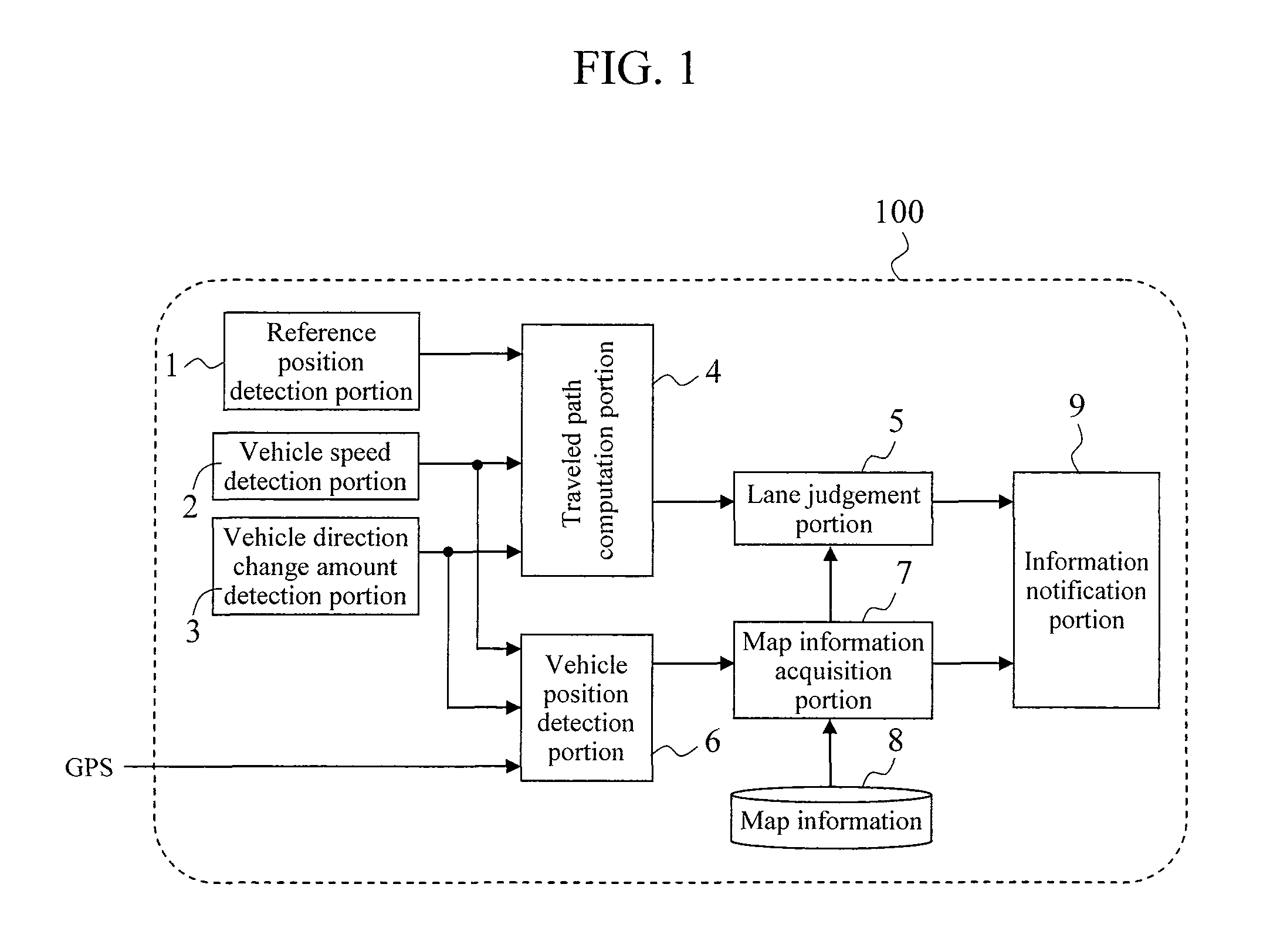
[0014]The present invention is made in view of the points above, and an object thereof is to provide lane judgement equipment and a navigation system that are capable of quickly and accurately judging the lane traveled by a vehicle that is traveling on a road with plural lanes in each direction so as to enable, for example, advanced route guidance by way of the navigation system.
[0016]According to the present invention, because the lane traveled is judged based on the entry distance and the map information, the entry distance being the road-width direction distance on the road with plural lanes in each direction from the reference position, which is set around the entrance to the road with plural lanes in each direction, up to the position of the vehicle on the road with plural lanes in each direction, the distance traveled before the lane traveled is judged can be shortened, and the errors that are accumulated in proportion to the length of the path traveled can be reduced.
[0017]It is thus possible to accurately determine which lane, on a road with plural lanes in each direction, the vehicle has entered and is traveling in, and to quickly and accurately judge the lane the vehicle is traveling in. Accordingly, advanced route guidance by a navigation system is made possible. For example, when traveling through consecutive intersections with short intervals in-between, since the lane the vehicle is traveling in can be judged immediately after turning at an intersection, appropriate route guidance at the next intersection is possible.

Problems solved by technology

However, with Patent Document 1, since a lane change is judged by detecting both a winker operation and white-line crossing, there is a risk of losing track of the position of the lane that the vehicle is traveling in as a result of forgetting to operate the blinker or of failing to detect the crossing of a white line.
In addition, because it is premised on white-line crossing, while it may be usable on highways and freeways, lane positions cannot be estimated based on white-line crossing at intersections on ordinary roads since there are no white lines within such intersections.
Thus, it is essentially unusable on roads with four or more lanes in each direction.
In addition, in order to detect dashed lines and dotted lines drawn with white lines, since the line kind is judged after detecting several strips of paint, there is a problem in that it takes some time before the lane can be judged.
Further, if the paint is worn off / eroded, it could cause detection failures or erroneous detections.
Still further, it is impractical since standards for line kinds would differ depending on the country of use.
Therefore, the estimation accuracy for the position of the vehicle is low, and it is not possible to attain positional accuracy that would allow for an accurate judgement of the lane that the vehicle is traveling in.
In particular, because the path traveled is derived from the current position of the vehicle that is calculated by the above-mentioned conventional calculation method, errors accumulate and the estimation accuracy for the position of the vehicle drops in proportion to the length of the path traveled.
In addition, because the lane traveled is determined based on the radius of turn during a left / right turn, when comparing, for example, a case where the vehicle travels straight up to about the center of an intersection and the steering wheel is fully turned at this position to turn with an extremely small radius, and a case where the steering wheel is gradually turned upon entering an intersection to turn within the intersection with a greater radius, there are significant influences caused by differences in how the vehicle is driven, and it is therefore impossible to attain positional accuracy that would allow for an accurate judgement of the lane the vehicle is traveling in.

Method used


Image

  • Lane Judgement Equipment and Navigation System
  • Lane Judgement Equipment and Navigation System
  • Lane Judgement Equipment and Navigation System

Examples


example 1

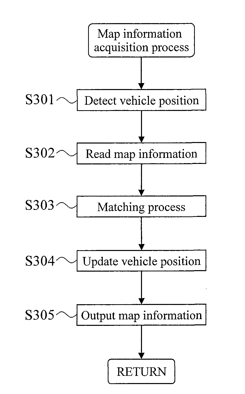
[0097]Next, using FIG. 5, a specific example of a lane judgement process of the navigation system 100 will be described in relation to a certain road condition.

[0098]FIG. 5 is a diagram illustrating a case in which, at intersection C where road A with one lane in each direction and road B with three lanes in each direction intersect, the vehicle 400 that is traveling on road A with one lane in each direction enters road B with three lanes in each direction by making a left turn at intersection C. It is noted that the vehicle 400 in this case travels through, in order, spots P1, P2, P3 and P4 to follow the path indicated with a solid line 401.

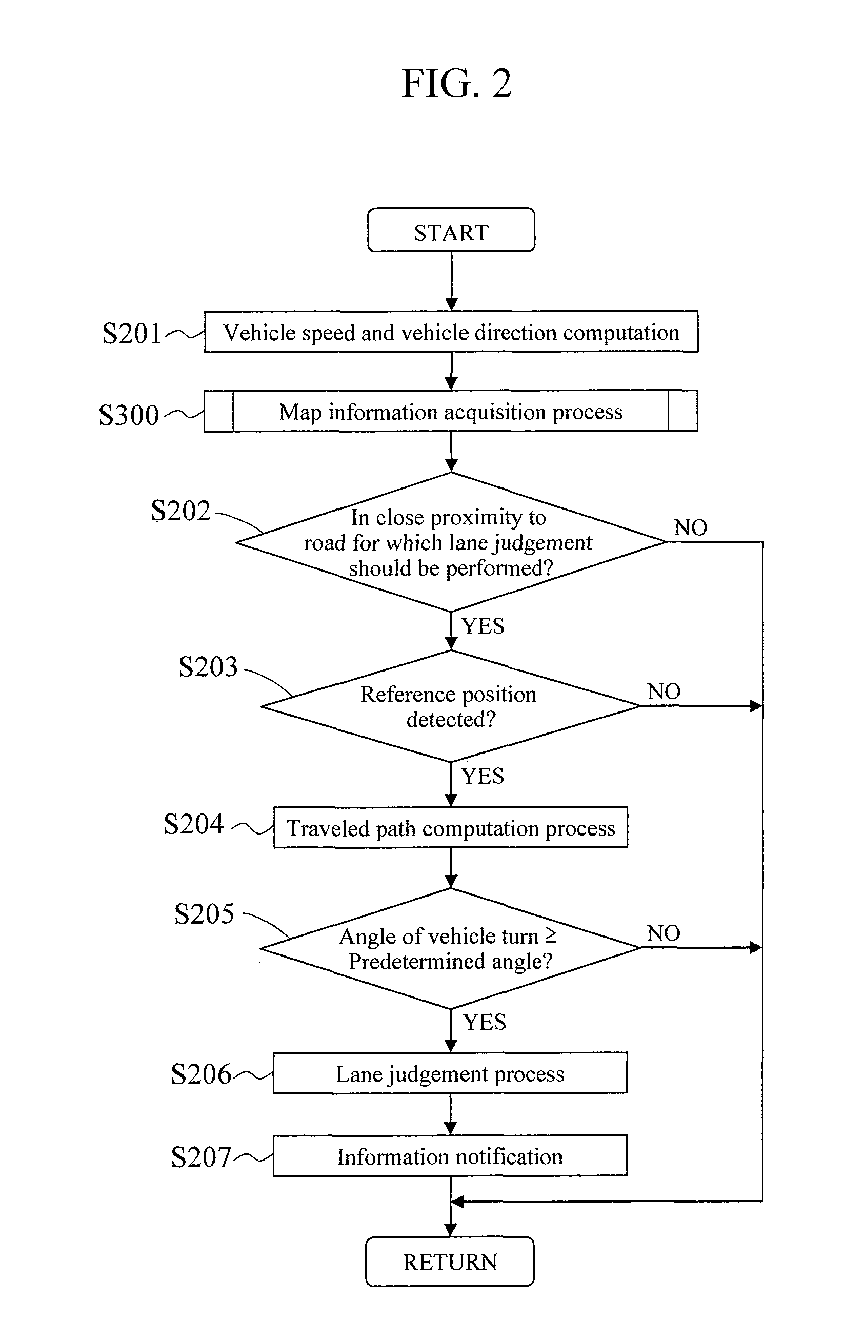
[0099]First, when the vehicle 400 is at spot P1, it is judged based on map information whether or not this spot P1 is in close proximity to a road for which lane judgement should be performed. Since road B which is about to be entered is a road with three lanes in each direction, it is judged that the vehicle 400 is in close proximity to a road ...

example 2

[0110]Next, using FIG. 6, Example 2 of a lane judgement process of the navigation system 100 will be described in relation to a certain road condition.

[0111]FIG. 6 is a diagram illustrating Example 2, indicating a case in which the vehicle 400 enters arterial road B with three lanes in each direction from alley D which is a narrow alley. It is noted that the vehicle 400 in this case travels through, in order, spots P1, P2, P3 and P4 to follow the path indicated with a solid line 501.

[0112]First, when the vehicle 400 is at spot P1, it is judged whether or not this spot P1 is in close proximity to a road for which lane judgement should be performed. Since road B is a road with plural lanes in each direction, it is judged that the vehicle 400 is in close proximity to a road for which lane judgement should be performed (YES in step S202), and the detection of a reference position is initiated. This judgement, as in Example 1, need only be performed in the vicinity of the entrance to roa...

example 3

[0119]Next, using FIG. 7, Example 3 of a lane judgement process of the navigation system 100 will be described in relation to a certain road condition.

[0120]FIG. 7 is a diagram illustrating Example 3, indicating a case in which a vehicle 700 enters arterial road B with three lanes in each direction from alley D which is a narrow alley. It is noted that the vehicle 700 in this case travels through, in order, spots P1, P2, P3 and P4 to follow the path indicated with a solid line 701.

[0121]First, when the vehicle 700 is at spot P1, it is judged whether or not this spot P1 is in close proximity to a road for which lane judgement should be performed. Since road B is a road with plural lanes in each direction, it is judged that the vehicle 700 is in close proximity to a road for which lane judgement should be performed (YES in step S202), and the detection of a reference position is initiated. This judgement, as in Example 1 and Example 2, need only be performed in the vicinity of the ent...


PUM


Abstract

There is provided lane judgement equipment that is capable of quickly and accurately judging the lane that a vehicle is traveling in on a road with plural lanes in each direction. Lane judgement equipment 100 detects reference positions 402, 502 that are set in advance at an entrance to road B with plural lanes in each direction, and judges which of lanes B1-B3 of road B with plural lanes in each direction a vehicle 400 is traveling in based on entry distance L from those reference positions 402, 502 and on map information.

Description

BACKGROUND OF THE INVENTION[0001]1. Field of the Invention[0002]The present invention relates to lane judgement equipment and navigation systems that judge which lane (vehicular lane) a vehicle is traveling in when the vehicle is traveling on a road with plural vehicular lanes in the same direction (hereinafter referred to as a road with plural lanes in each direction) such as so-called two-lane roads, three-lane roads, and the like.[0003]2. Background Art[0004]Navigation systems that are mounted on automobiles have functions for displaying the position of a vehicle, which is detected by such autonomous methods as a GPS (Global Positioning System), a gyrosystem, and the like, along with map information for the surroundings thereof.[0005]The closer the vehicle position displayed on the navigation system is to the actual vehicle position, the higher the positional accuracy is. When a highly accurate vehicle position is outputted, passengers are able to obtain appropriate road informat...

Claims


Application Information

Patent Timeline
IPC IPC(8): G01C21/26G01C21/00G01C21/28G08G1/16
CPCB60W30/12B60W40/072B60W2550/402B60W2520/10B60W2550/141B60W40/076B60W2556/50B60W2552/05B60W2540/18G01C21/00
Inventor IMAI, MASATOHOSHINO, MASATOSHISAKATA, MASAO
Owner CLARION CO LTD
Learn More