

Vehicle steering apparatus
- Summary
- Abstract
- Description
- Claims
- Application Information
AI Technical Summary
Benefits of technology
Problems solved by technology
Method used
Image

Examples
Embodiment Construction
[0068]Referring to the drawings, embodiments of the present invention will be specifically described.
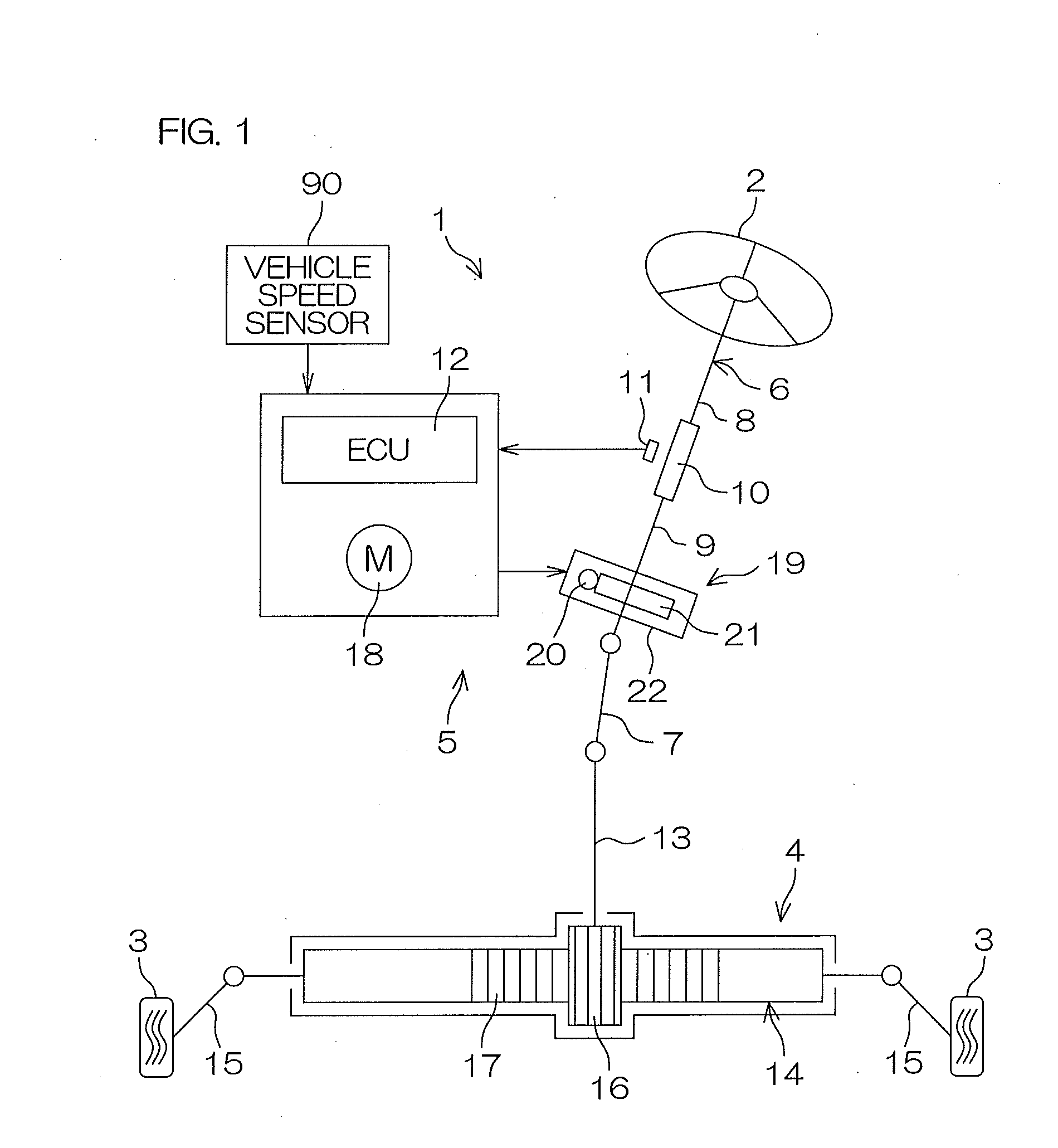
[0069]FIG. 1 is a schematic view illustrating the schematic configuration of an electric power steering apparatus 1 serving as a vehicle steering apparatus according to an embodiment of the present invention.
[0070]Referring to FIG. 1, the electric power steering apparatus 1 includes a steering wheel 2 serving as a steering member, a steering mechanism 4 for steering steerable wheels 3 in synchronization with the rotation of the steering wheel 2, and a steering assist mechanism 5 for assisting a driver in steering. The steering wheel 2 and the steering mechanism 4 are mechanically connected to each other via a steering shaft 6 and an intermediate shaft 7.
[0071]Although in the present embodiment, the steering assist mechanism 5 applies an assist force (a steering assist force) to the steering shaft 6, the present invention can be applied to a configuration in which the steering assist ...
PUM
 Abstract
Description
Claims
Application Information