Quad tilt rotor aerial vehicle with stoppable rotors

a technology of stoppable rotors and quadrotors, which is applied in the direction of rotocraft, vertical landing/take-off aircraft, remote control aircraft, etc., can solve the problems of limiting the maximum speed of the aircraft, poor hover efficiency, excessive vibration, etc., and achieves the effect of increasing the vehicle maneuverability and fuselage attitude control, and increasing the aerodynamic efficiency of the vehicl

Inactive Publication Date: 2011-01-06
FORGAC PAVOL
View PDF35 Cites 230 Cited by
  • Summary
  • Abstract
  • Description
  • Claims
  • Application Information

AI Technical Summary

Benefits of technology

[0011]During VTOL and hover, all four rotors are tilted substantially vertically to provide lift. In the preferred embodiment, the larger (main) rotors provide during the rotor-borne flight virtually all the lift while the smaller rotors (propellers) serve mainly for the vehicle (fuselage) attitude control. Thus, the vehicle can be controlled only by the tilt and collective pitch of main rotors and propellers, eliminating the need for cyclic pitch control.
[0012]The vehicle is equipped also with two pairs of airfoil section wings substantially normal to fuselage (same as on other QTR aircraft). At sufficiently high vehicle airspeed, these wings provide the vehicle flight sustainment lift, upon which the tilt-rotors can be tilted from substantially vertical to substantially horizontal position and the main rotors can be feathered and stopped. Having only smal...

Problems solved by technology

As is known to those skilled in design of such vehicles, they suffer from various deficiencies, such as aeroelastic instability limiting their maximum speed, poor hover efficiency, excessive vibrations and larger noise levels due to large prop-rotors.
Folding the bla...

Method used


Image

  • Quad tilt rotor aerial vehicle with stoppable rotors
  • Quad tilt rotor aerial vehicle with stoppable rotors
  • Quad tilt rotor aerial vehicle with stoppable rotors

Examples


Embodiment Construction

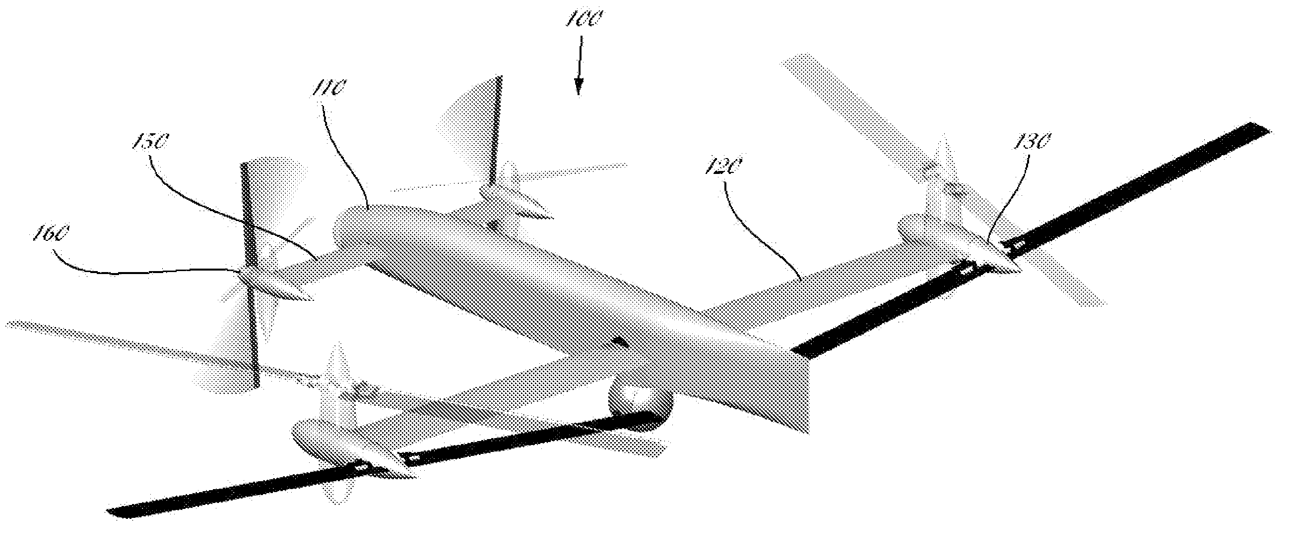
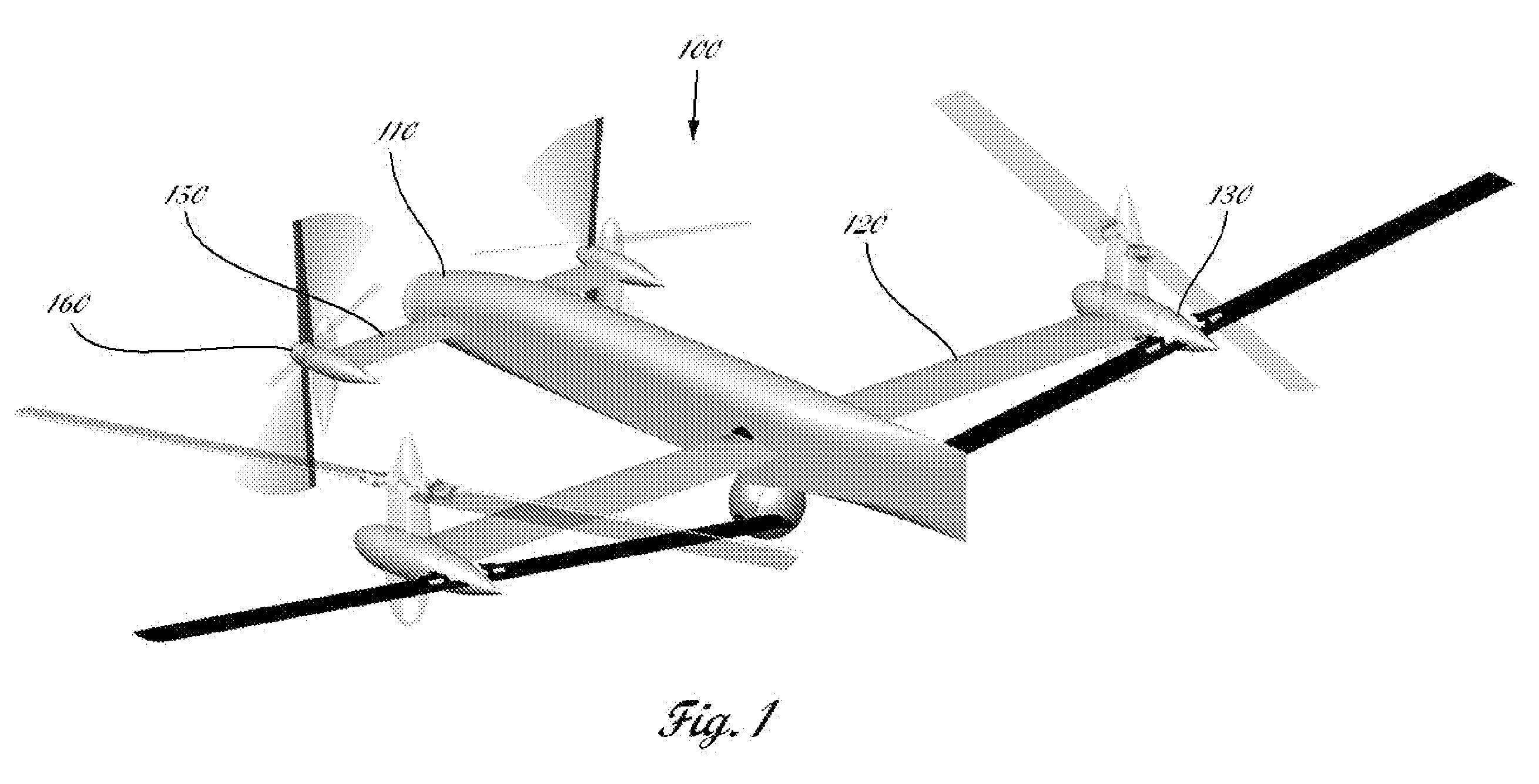
[0019]The exemplary aerial vehicle illustrated in FIGS. 1-3 is capable of vertical takeoff and landing, hover, and low speed flight with agile maneuvering while operating as a rotary wing aircraft, and efficient high-speed flight when operating as a fixed wing aircraft.

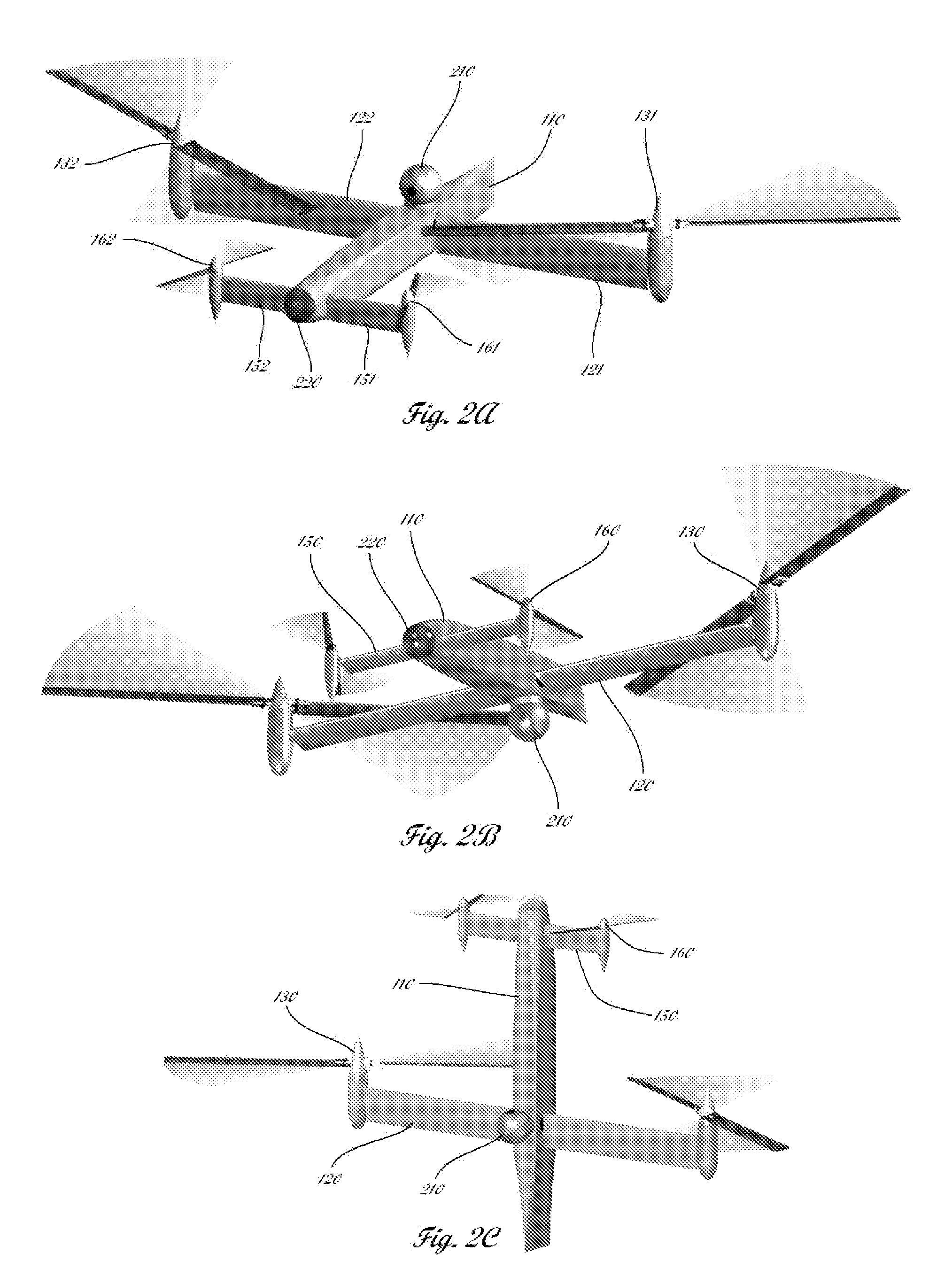
[0020]The vehicle 100 consists of a fuselage 110 with a pair of main wings 120 and tip mounted main rotors 130 attached to the central or aft section of the fuselage. To the front section of the fuselage is attached a pair of elevators 150 and propellers 160. In the preferred embodiment shown in FIGS. 1-4, the main wings 120 and main rotors 130 are significantly larger than the elevators 150 and propellers 160. However, rotors of equal size can be employed in other embodiments of the disclosed invention too.

[0021]The main rotors 130 and propellers 160 can be tilted from substantially vertical position for rotor-borne flight to substantially horizontal position for high speed wing-borne flight, as shown in FIG. 1. Duri...


PUM


Abstract

The disclosed invention consists of several improvements to well known Quad Tilt-Rotor (QTR) aircraft. The first is that during a wing-borne flight, one pair of tilt-rotors, which can be substantially larger than the other pair, is feathered and stopped. This can promote vehicle aerodynamic efficiency and can be utilized to increase vehicle speed. Second is that the wings are not attached to the fuselage at a fixed angle of incidence like on conventional QTR aircraft, but can also be tilted in respect to the fuselage independently of the tilt-rotors. Furthermore, each rotor and each wing can be tilted with respect to fuselage to any tilt-angle without limit, which gives the vehicle unprecedented ability to position the fuselage in any attitude in respect to the vehicle direction of flight.

Description

CROSS-REFERENCE TO RELATED APPLICATIONS[0001]This Application is a non-provisional application of provisional (35 USC 119(e)) application 61 / 222,741 filed in the United States on Jul. 2, 2009, the entire disclosure of which is incorporated by reference herein.STATEMENT REGARDING FEDERALLY SPONSORED RESEARCH OR DEVELOPMENT[0002]Not ApplicableREFERENCE TO SEQUENCE LISTING, A TABLE, OR A COMPUTER PROGRAM LISTING COMPACT DISC APPENDIX[0003]Not ApplicableBACKGROUND OF THE INVENTION[0004]Tilt-rotor aerial vehicles are well known and used both in military (e.g., Bell / Boeing V-22 Osprey) and in civilian applications (Bell Augusta BA-609). As is known to those skilled in design of such vehicles, they suffer from various deficiencies, such as aeroelastic instability limiting their maximum speed, poor hover efficiency, excessive vibrations and larger noise levels due to large prop-rotors.[0005]To eliminate or reduce these deficiencies, several approaches have been considered by prior art. One ...

Claims


Application Information

Patent Timeline
IPC IPC(8): B64C27/26
CPCB64C29/0033B64C2201/127B64C2201/088B64C39/024B64U70/80B64U2101/30B64U10/25B64U50/19
Inventor FORGAC, PAVOL
Owner FORGAC PAVOL
Why Eureka
Try Eureka