Network Cabinet Fitting System

Inactive Publication Date: 2011-01-06
PANDUIT
View PDF33 Cites 26 Cited by
  • Summary
  • Abstract
  • Description
  • Claims
  • Application Information

AI Technical Summary

Benefits of technology

[0005]The present invention is directed to a fitting system that seals openings in the top of a network cabinet to improve cooling of the network equipment located in the network cabinet. The fitting system includes a grommet, a fitting assembly and a filler panel. The grommet is secured in one of the openings in the top of the network cabinet. The fitting assembly

Problems solved by technology

When cables are run in or out of the cabinet, air within the cabinet may escape throug

Method used


Image

  • Network Cabinet Fitting System
  • Network Cabinet Fitting System
  • Network Cabinet Fitting System

Examples


Example

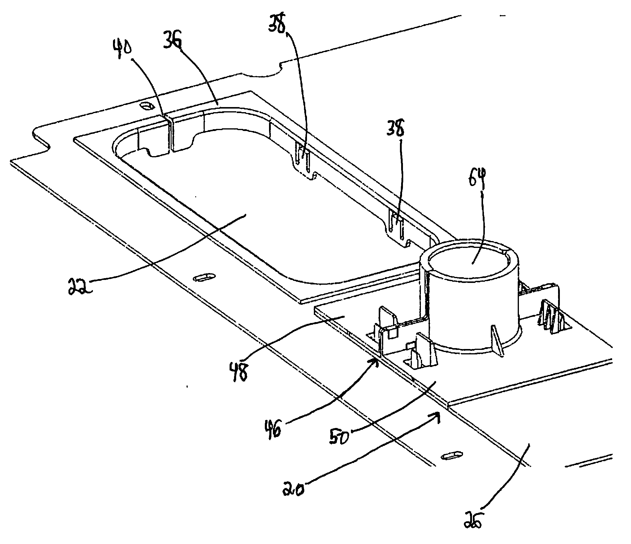
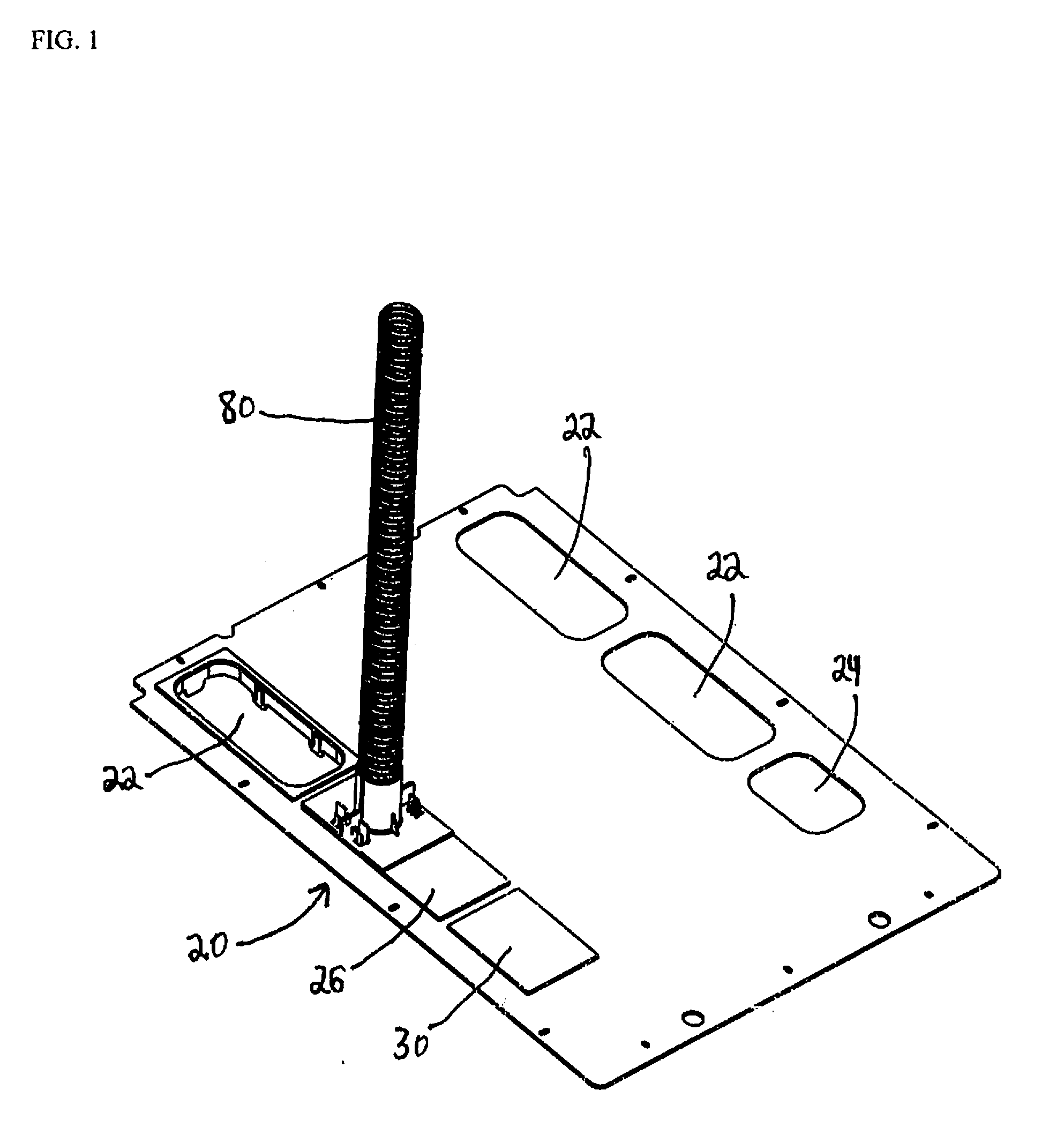
[0024]FIGS. 1-18 illustrate a fitting system 20 secured to the top of a network cabinet. The network cabinet may include various types of servers, switches and other electronic equipment. Preferably, the network cabinet is Panduit Corp.'s Net-Access™ network cabinet disclosed in U.S. Pat. No. 7,498,512, the disclosure of which is incorporated by reference in its entirety. Fitting system 20 may also be used with other network cabinets.

[0025]As shown in FIG. 1, the network cabinet includes four large 22 and two small 24 openings for routing power, copper and fiber cables. However, the network cabinet may include any number of large and small openings. Although FIG. 1 shows fitting system 20 secured within opening 22, it is likewise contemplated that fitting system 20 may be secured within opening 24. When fitting system 20 is secured within opening 24, filler panel 26 is not necessary.

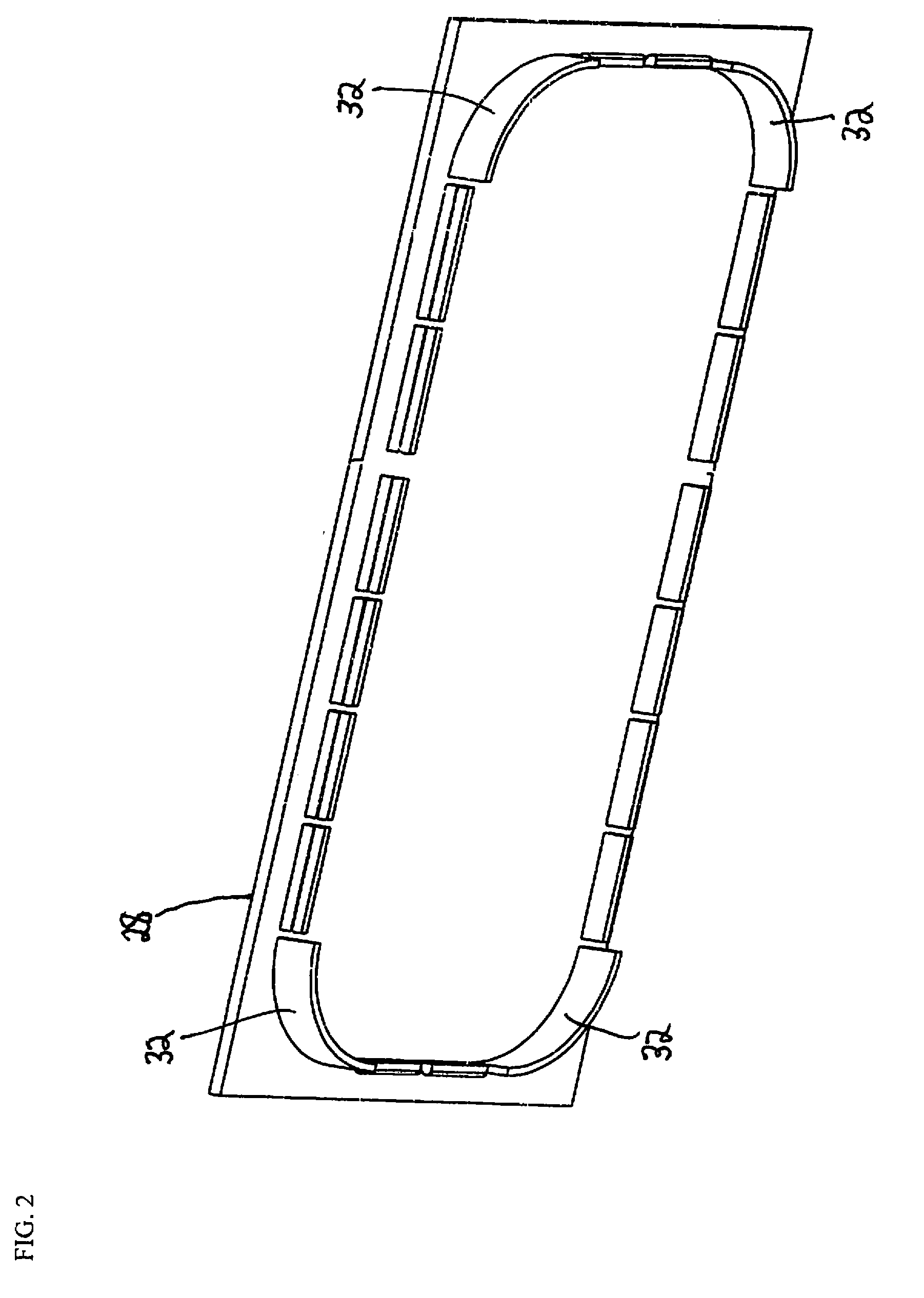
[0026]Covers 28, 30 are positioned within large 22 and small 24 openings, respectively. Preferably, c...


PUM


Abstract

A network cabinet fitting system includes a grommet, a corrugated tube fitting assembly and a filler panel. The grommet and the filler panel are installed within an opening of a network cabinet top. The fitting assembly is secured around a corrugated tube and inserted into the grommet to seal the opening.

Description

CROSS-REFERENCE TO RELATED APPLICATIONS[0001]This application claims priority to U.S. Provisional Application No. 61 / 223,126, filed Jul. 6, 2009, the subject matter of which is hereby incorporated by reference in its entirety.BACKGROUND OF THE INVENTION[0002]The present invention relates to a network cabinet fitting system and, more particularly, to a fitting system that is secured to a top opening of a network cabinet for fiber cables passing through a corrugated tube.[0003]Typically, network cabinets have knockouts or removable openings of various sizes to allow cables to enter and exit the cabinet. When cables are run in or out of the cabinet, air within the cabinet may escape through the openings and around the cables and adversely affect the cabinet cooling systems.[0004]Therefore, there is a need for a network cabinet fitting system that seals around cables to reduce air leaks.SUMMARY[0005]The present invention is directed to a fitting system that seals openings in the top of ...

Claims


Application Information

Patent Timeline
IPC IPC(8): H05K5/02A47B95/00F16L41/12
CPCH02G3/0691G02B6/4471
Inventor CAVENEY, JACK E.HARTMAN, SCOTT R.
Owner PANDUIT
Why Eureka
Try Eureka