
Interface element, interface element holder, and electrical appliance

Active Publication Date: 2011-01-06
ROBERT BOSCH GMBH
View PDF9 Cites 17 Cited by
  • Summary
  • Abstract
  • Description
  • Claims
  • Application Information

AI Technical Summary

Benefits of technology

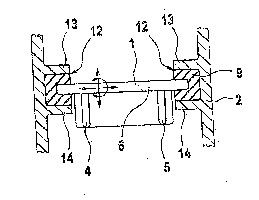
[0009]The invention is based on the concept of providing a positioning section composed of an elastic material that permits the hard component section of the interface element to move relative to the interface element holder. In this connection, the scope of the invention includes providing the positioning section on the interface element and / or on the interface element holder. It is only essential for the positioning section to be composed of a material that is more elastic (softer) than that of the hard component section of the interface element. In other words, the invention is comprised of providing a positioning section that is composed of an elastic material between the hard component section of the interface element and a hard component section of the interface element holder; this positioning section, due to its inherent elastic deformation, permits a relative movement between the two hard component sections of the interface partners. The embodiment of the positioning section out of an elastic material preferably permits the hard component section of the interface element to move relative to the interface element holder along all spatial axes. In addition, the elastic positioning section advantageously also permits a swiveling motion of the hard component section around at least one, but preferably all three, spatial axes. An interface element embodied according to the concept of the invention or an interface element holder embodied according to the concept of the invention combines only the advantages of a play-free positioning and a floating positioning, while avoiding their disadvantages. Thus on the one hand, it is possible to exactly position the interface partners relative to each other and at the same time, the resistance to soiling is increased. In other words, the relative movement function of the positioning section is not restricted due to soiling that occurs over the course of the service life since the relative movement between the at least one hard component section of the interface element and the at least one hard component section of the interface element holder is implemented only by means of an (internal) material deformation of the positioning section and not by means of a sliding relative movement. In addition, a greater mechanical strength is achieved than with a positioning that is play-free and floats in a sliding fashion. Furthermore, the mechanical ruggedness, in particular the ultimate strength, is increased due to the shock absorption function of the positioning section. In particular, the presence of the positioning section achieves an improved damping behavior. This in turn results in an improved vibration resistance as compared to known positioning mechanisms. Furthermore, the accuracy of fit is optimized in comparison to known floating positioning mechanisms. Moreover, the tolerance limits to be respected can be loosened due to the fact that the positioning section is composed of an elastic material.

Problems solved by technology

Interface partners that can be positioned relative to each other in a floating fashion as a rule have the disadvantage of an insufficient resistance to soiling, which causes the interface partners to lose their ability to move relative to each other over time, with the result that the interface partners can no longer sufficiently fulfill their functions.
On the other hand, a fixed, play-free positioning has the disadvantage that there is no possibility at all of adjusting the interface partners relative to each other, thus limiting the utilization range of a play-free positioning.
In general, all known interface partners have the disadvantage that sudden stresses are absorbed by hard component sections and, particularly in the case of long-lasting stress, lead to fracturing or other types of damage.

Method used


Image

  • Interface element, interface element holder, and electrical appliance
  • Interface element, interface element holder, and electrical appliance
  • Interface element, interface element holder, and electrical appliance

Examples


Embodiment Construction

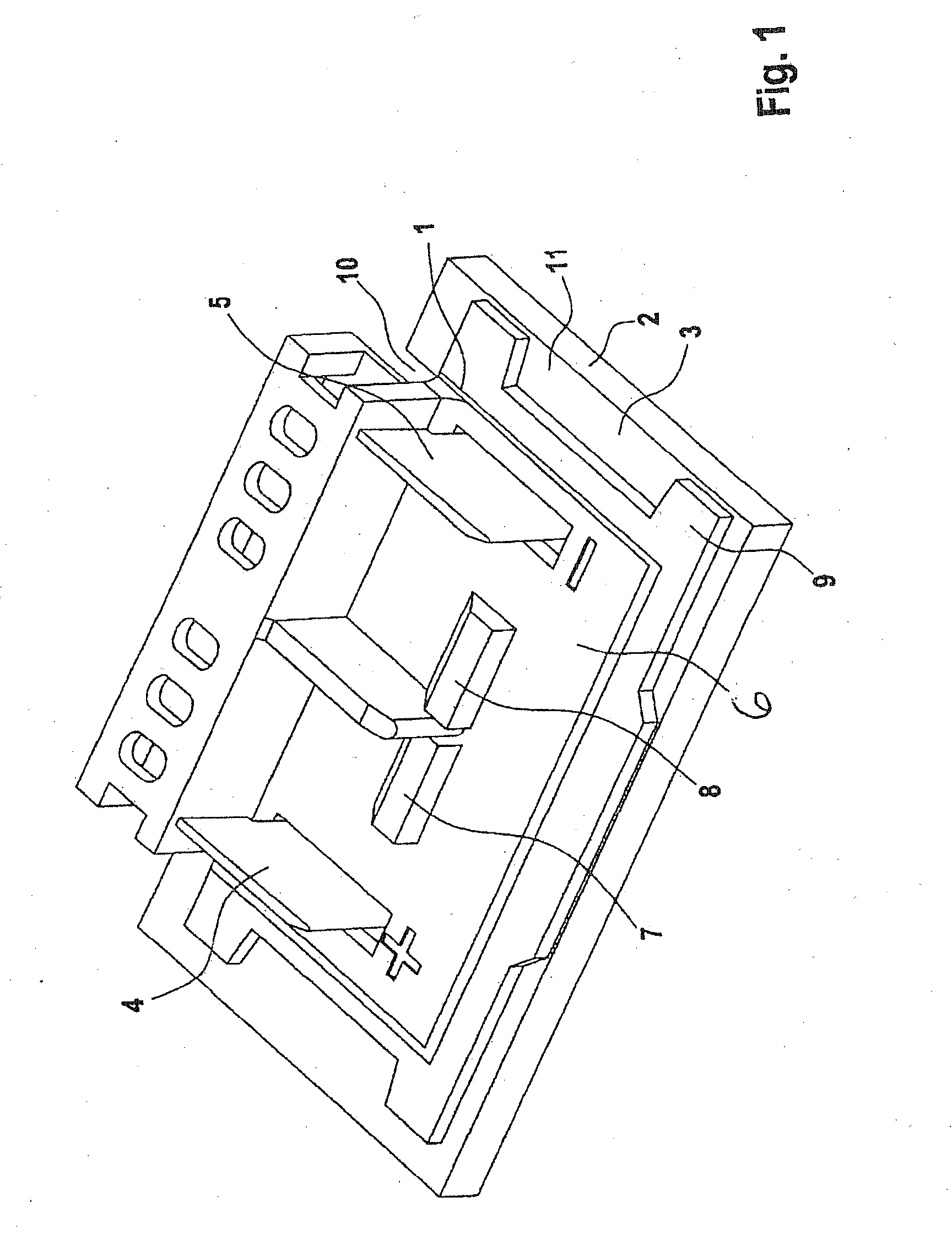
[0023]In the drawings, components that are the same or have the same function are labeled with the same reference numerals.

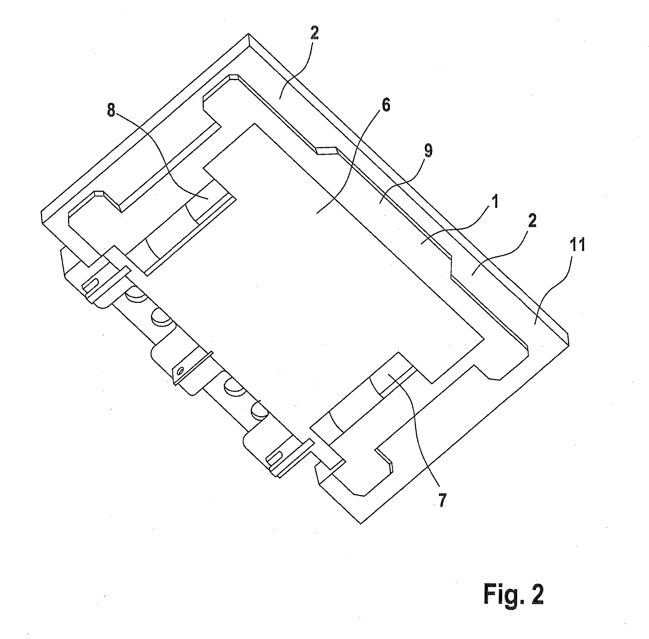
[0024]FIG. 1 shows an arrangement composed of an interface element embodied as an electrical interface element 1 and an interface element holder 2 that holds the interface element 1. In the exemplary embodiment shown, the interface element holder 2 is a component of a housing 3 of an electrical appliance that is not shown in detail, including an electric drive motor that is likewise not shown.

[0025]The interface element 1, which is permanently held in the interface element holder 2 once they are assembled, cooperates with functional sections 4, 5 embodied in the form of electrical contacts to produce the electrical contact between rechargeable batteries, not shown, and the electric drive motor, likewise not shown, of the electrical appliance.

[0026]The drawing shows a hard component section 6 of the interface element 1 with which the functional elements 4, 5 embo...


PUM


Abstract

The invention relates to an interface element to be fixed on and / or in an interface element holder of an electrical appliance, which element includes a hard component portion. The invention provides a positioning portion which is formed from an elastic material and makes it possible for the hard component portion to move relative to the interface element holder as a result of deformation. The invention also relates to an interface element holder and to an electrical appliance.

Description

PRIOR ART[0001]The invention relates to an interface element according to the preamble to claim 1, an interface element holder according to claim 6, an electrical appliance according to claim 10, and a use according to claim 11.[0002]Interface elements, which necessarily also include interface element assemblies, are used for an extremely wide variety of functions in electrical appliances. They are used wherever two parts, namely the interface element and an interface element holder are to be placed against each other or one inside the other. Frequently, an interface element is a battery tray cover for closing a battery tray (interface element holder) of an electrical appliance or is an (electrical) interface between a battery tray and an electric drive unit or set of electronics. Such interface elements customarily have electrical contacts that are affixed, usually by means of extrusion coating, to the interface element that is composed of hard plastic. In addition to or in lieu of...

Claims


Application Information

Patent Timeline
IPC IPC(8): H01R13/66F16B2/22
CPCB25F5/006Y10T403/54B25F5/02
Inventor REJMAN, MARCIN
Owner ROBERT BOSCH GMBH
Learn More