Bone joining apparatus and method

a bone and joint technology, applied in the field of bone joining devices and methods, can solve the problems of pain, mtp and dip joints are often compensated for hyperextension, and often require pip fusion or joint replacemen

Active Publication Date: 2011-01-06
ZIMMER INC
View PDF61 Cites 144 Cited by
  • Summary
  • Abstract
  • Description
  • Claims
  • Application Information

AI Technical Summary

Benefits of technology

[0011]Additionally, a driver suitable for screwing the above-described device into an intramedullary canal of a bone is provided. The device comprises an elongate shank having a proximal end and a distal end. The distal end comprises two half sections operably linked to a slidable bobbin on the shank, such that sliding the bobbin toward the distal end forces the two half sections together to hold the first top or the second top securely.

Problems solved by technology

Progressive PIP joint flexion deformity typically leads to compensatory hyperextension of the MTP and DIP joints.
Pain occurs due to rubbing of the prominence against the patient's shoe.
However, when the deformity is fixed, PIP fusion or joint replacement is often required.
With all current implants, placement is critical because, when mounted, there is no adjustability in the angle of flexion between the two cut bones to be joined.

Method used


Image

  • Bone joining apparatus and method
  • Bone joining apparatus and method
  • Bone joining apparatus and method

Examples


Embodiment Construction

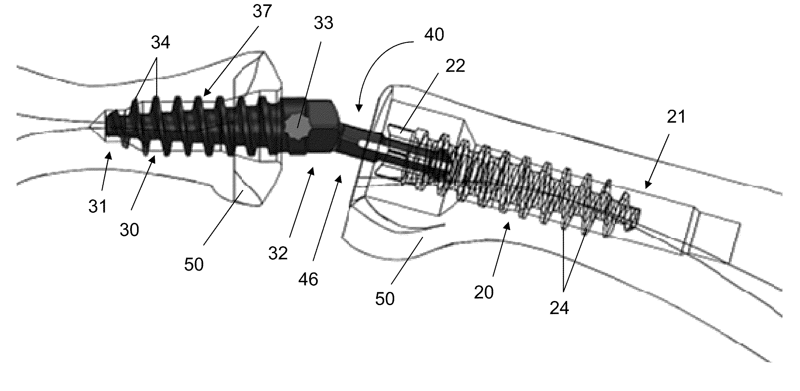
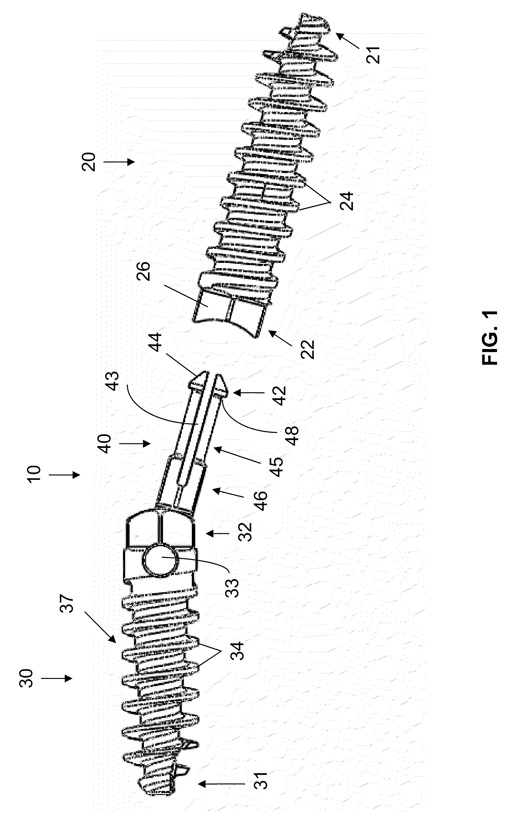
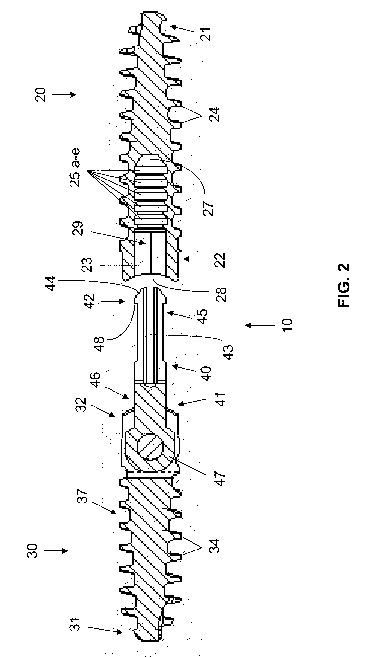
[0047]The inventors have developed a bone joining device that allows adjustment of the angle between the two bones to be joined.

[0048]In some embodiments, the application is directed to a bone joining device suitable for joining a first bone piece to a second bone piece. The device comprises a first component and a second component, wherein the first component comprises a first elongated stem portion comprising a first end and a first top opposite the first end, the first elongated stem portion suitable for insertion from the first end longitudinally into a surface of the first bone piece, and the second component comprises a second elongated stem portion comprising a second end and a second top, the second elongated stem portion suitable for insertion from the second end longitudinally into a surface of the second bone piece. The device further comprises a connector extending from the second top. The connector is capable of joining with the first component and locking therewith.

[00...


PUM


Abstract

Provided is a bone joining device suitable for joining a first bone piece to a second bone piece. Also provided is a method of joining a first bone piece with a second bone piece in a living mammal. The method comprises inserting the above bone joining device between the first bone piece and the second bone piece.

Description

CROSS-REFERENCE TO RELATED APPLICATIONS[0001]This application claims the benefit of U.S. Provisional Application No. 61 / 153,907, filed Feb. 19, 2009, which is incorporated herein by reference in its entirety.BACKGROUND[0002](1) Field[0003]This application relates to devices and methods for joining bones.[0004](2) Description of the Related Art[0005]Hammertoe deformity, the most common deformity of the lesser toes, is a flexion deformity of the proximal interphalangeal (PIP) joint of the toe, with hyperextension of the metatarsophalangeal (MTP) and distal interphalangeal (DIP) joints. Progressive PIP joint flexion deformity typically leads to compensatory hyperextension of the MTP and DIP joints. This makes the PIP joint prominent dorsally. Pain occurs due to rubbing of the prominence against the patient's shoe. The deformity is flexible at first but usually becomes fixed over time. When the deformity is flexible, various procedures can be utilized that involve manipulation of the in...

Claims


Application Information

Patent Timeline
Patent Type & Authority Applications(United States)
IPC IPC(8): A61B17/86A61B17/56A61B17/16
CPCA61B17/1682A61B17/8685A61B17/86A61F2/4225A61F2/4606A61F2002/30205A61F2002/30331A61F2002/30481A61F2002/30487A61F2002/30497A61F2002/30538A61F2002/30551A61F2002/30622A61F2002/30624A61F2002/3085A61F2002/30874A61F2002/423A61F2002/4235A61F2220/0025A61F2220/0033A61F2230/0067A61F2250/0006A61B17/7291A61B17/68A61F2002/30495A61F2002/3055A61F2002/30873A61F2002/4228A61F2002/4233A61B17/82A61F2/30A61F2/42
Inventor WEINER, LONKATCHIS, STUART D.ALFARO, ARTHUR A.TRUMAN, MARI S.VAN IPEREN, WILLEM H.P.
Owner ZIMMER INC
Why Eureka
Try Eureka