
Refrigeration apparatus

Inactive Publication Date: 2011-01-13
DAIKIN IND LTD
View PDF15 Cites 5 Cited by
  • Summary
  • Abstract
  • Description
  • Claims
  • Application Information

AI Technical Summary

Benefits of technology

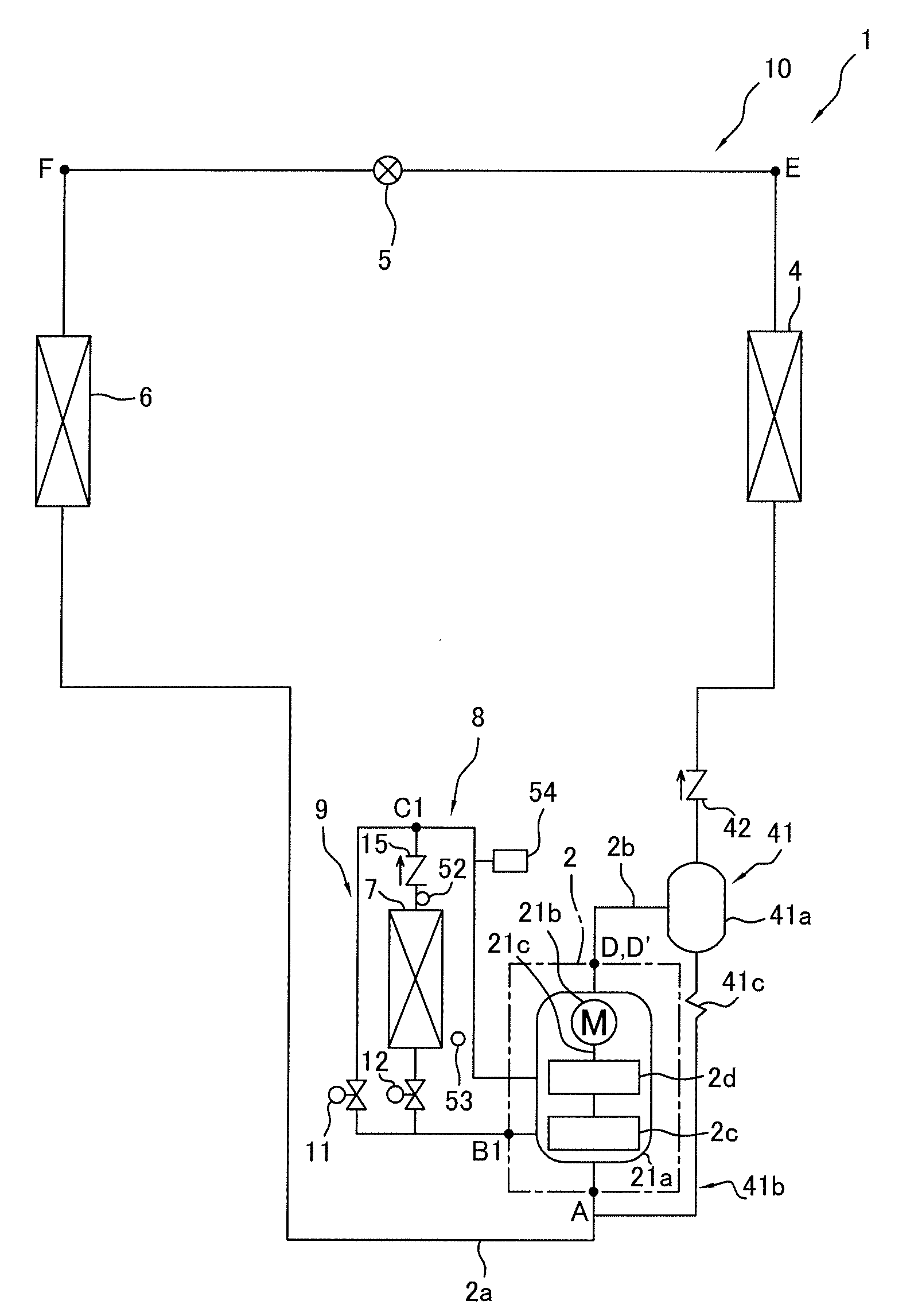
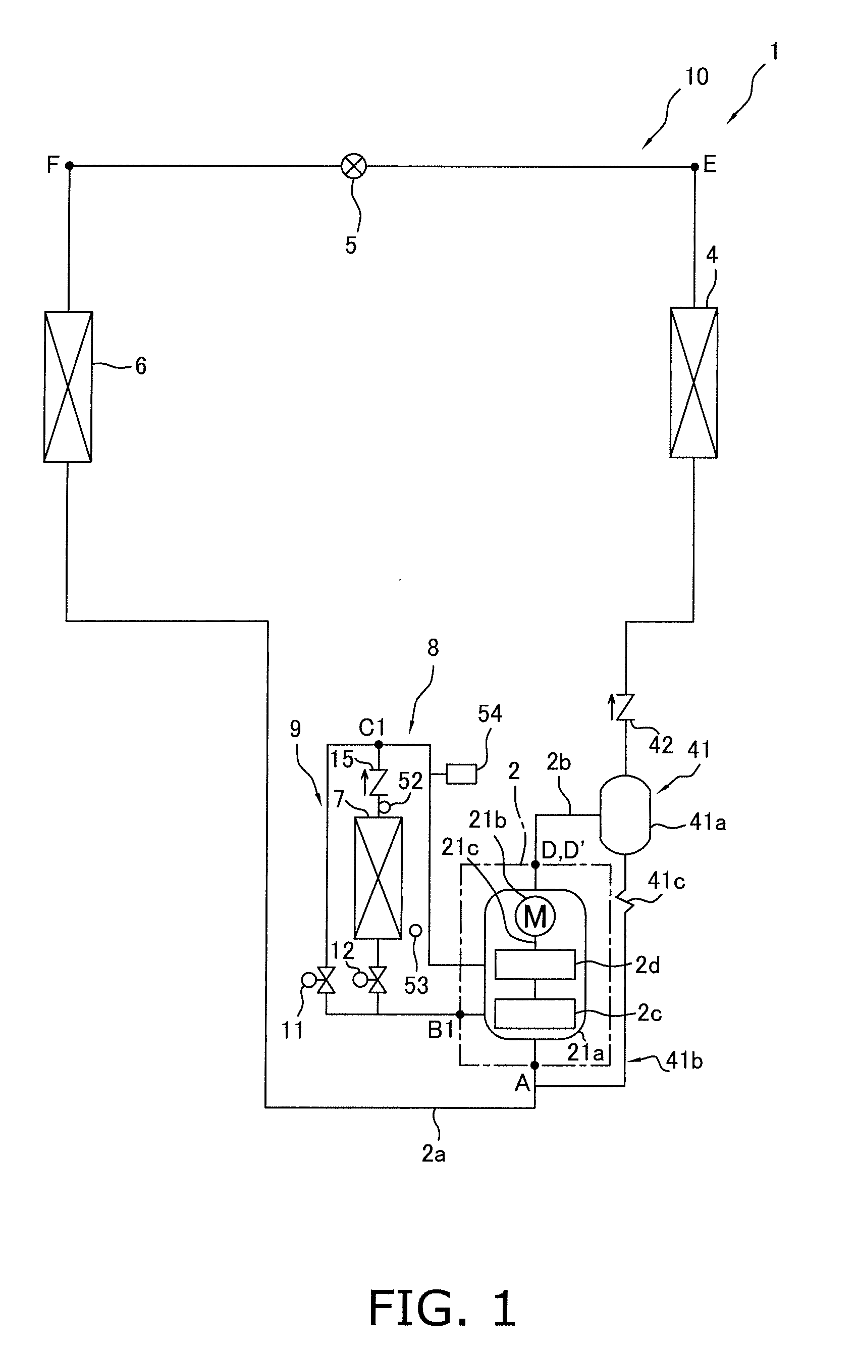
[0007]As a countermeasure to such problems, the intercooler which functions as a cooler of the refrigerant discharged from the first-stage compression element and drawn into the second-stage compression element is provided to the intermediate refrigerant tube for drawing refrigerant discharged from the first-stage compression element into the second-stage compression element, thereby lowering the temperature of the refrigerant drawn into the second-stage compression element. As a result, the temperature of the refrigerant discharged from the second-stage compression element is reduced, and a reduction in heat radiation loss in the outdoor heat exchanger is conceivable.
[0024]In addition to cooling the refrigerant drawn into the second-stage compression element by the intercooler, the refrigeration apparatus can reduce the temperature of the refrigerant drawn into the second-stage compression element by intermediate injection using a second-stage injection tube. Therefore, the temperature of the refrigerant discharged from the compression mechanism can be kept low, and the power consumption of the compression mechanism can be reduced.

Problems solved by technology

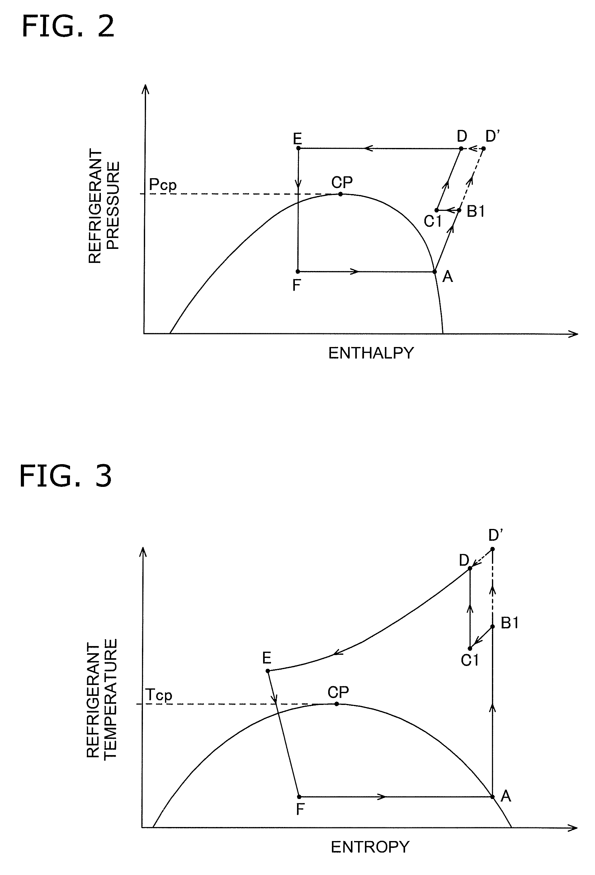
However, in such a configuration, the refrigerant discharged from the first-stage compression element and drawn into the second-stage compression element is liable to be excessively cooled under operating conditions in which the temperature of the water and / or air as the heat source of the intercooler is low.
Therefore, the refrigerant drawn into the second-stage compression element becomes wet, and the reliability of the compressor is liable to be compromised.

Method used


Image

  • Refrigeration apparatus
  • Refrigeration apparatus
  • Refrigeration apparatus

Examples


modification 1

(3) Modification 1

[0071]In the embodiment described above, a heat exchanger is used as the intercooler 7 in which air is the heat source, but a heat exchanger may be used as the intercooler 7 in which water is used as the heat source.

[0072]For example, in a configuration that feeds water to the intercooler 7 via a water distribution tube 14 for intermediate cooling, as shown in FIG. 4, wet prevention control may be carried out so that a determination is made as to whether the temperature of the water (in this case, the temperature of the water fed to the intercooler 7 detected by a water temperature sensor 58 disposed in the water inlet side of the intercooler 7) as the heat source of the intercooler 7 is equal to or less than the saturation temperature of the intermediate-pressure refrigerant fed from the first-stage compression element 2c to the second-stage compression element 2d, or whether the temperature of the refrigerant (in this case, the temperature of the refrigerant dete...

modification 2

(4) Modification 2

[0076]Modification 1 described above is configured so that water is fed to the intercooler 7 via a water distribution tube 14 for intermediate cooling and so that a water on / off valve 14a is provided to the water distribution tube 14 for intermediate cooling; and in the case that it has determined that the temperature of the water as the heat source of the intercooler 7 or temperature of the refrigerant in the outlet of the intercooler 7 is equal to or less than the saturation temperature of the refrigerant fed from the first-stage compression element 2c to the second-stage compression element 2d, wet prevention control is carried out by allowing intermediate-pressure refrigerant not to flow to the intercooler 7 by using a intercooler bypass tube 9 and water fed to the intercooler 7 is stopped by closing the water on / off valve 14a (see FIG. 5). However, it is also possible to omit the intercooler bypass tube 9 including the intercooler bypass on / off valve 11, and / o...

modification 3

(5) Modification 3

[0078]In the configuration of Modification 2 described above (see FIG. 6), it is also possible to use a configuration in which the water on / off valve 14a is composed of a valve whose degree of opening can be adjusted, and when it has been determined that the temperature of the refrigerant in the outlet of the intercooler 7 is equal to or less than the saturation temperature of the refrigerant fed from the first-stage compression element 2c to the second-stage compression element 2d, wet prevention control is carried out so as to reduce the flow rate of water fed to the intercooler 7 by reducing the degree of opening of the water on / off valve 14a to prevent the refrigerant drawn into the second-stage compression element 2d from becoming wet, and furthermore so as to control the flow rate of the water that flows through the intercooler 7 so that the temperature of the refrigerant in the outlet of the intercooler 7 become greater than the saturation temperature of the...


PUM


Abstract

A refrigeration apparatus includes a compression mechanism, a heat source-side heat exchanger, a usage-side heat exchanger and an intercooler. The compression mechanism has compression elements arranged so that refrigerant discharged from a first-stage compression element is sequentially compressed by a second-stage compression element. The intercooler is connected to an intermediate refrigerant tube arranged and configured to draw refrigerant discharged from the first-stage compression element into the second-stage compression element. The intercooler is arranged and configured to cool the refrigerant discharged from the first-stage compression element and drawn into the second-stage compression element. The intercooler and the intermediate refrigerant tube and are arranged and configured to perform wet prevention control when a heat source temperature of the intercooler or an outlet refrigerant temperature of the intercooler is equal to or less than a saturation temperature of the refrigerant fed from the first-stage compression element to the second-stage compression element.

Description

TECHNICAL FIELD[0001]The present invention relates to a refrigeration apparatus, and particularly relates to a refrigeration apparatus which performs a multistage compression refrigeration cycle.BACKGROUND ART[0002]As one conventional example of a refrigeration apparatus which performs a multistage compression refrigeration cycle, Patent Document 1 discloses an air-conditioning apparatus which performs a two-stage compression refrigeration cycle. This air-conditioning apparatus primarily has a compressor having two compression elements connected in series, an outdoor heat exchanger, an expansion valve, and an indoor heat exchanger.[0003]<Patent Document 1>[0004]Japanese Laid-open Patent Application No. 2007-232263DISCLOSURE OF THE INVENTION[0005]The refrigeration apparatus according to a first aspect of the present invention comprises a compression mechanism, a heat source-side heat exchanger, a usage-side heat exchanger, and an intercooler, and an intercooler bypass tube. The...

Claims


Application Information

Patent Timeline
IPC IPC(8): F25B1/10F25B41/00
CPCF25B1/10F25B9/008F25B13/00F25B2309/061F25B2313/0272F25B2313/02741F25B2700/21F25B2400/072F25B2400/075F25B2400/13F25B2400/23F25B2500/28F25B2400/04
Inventor FUJIMOTO, SHUJIYOSHIMI, ATSUSHI
Owner DAIKIN IND LTD
Learn More