Liquid delivery control method and liquid delivery control system

a control method and control system technology, applied in water supply installation, laboratory glassware, instruments, etc., can solve the problems of complex structure of the cartridge b>92/b> and the risk of the liquid b>98/b> being electrolyzed by this curren

Inactive Publication Date: 2011-01-13
ARKRAY INC
View PDF9 Cites 3 Cited by
  • Summary
  • Abstract
  • Description
  • Claims
  • Application Information

AI Technical Summary

Benefits of technology

[0008]An object of the present invention, which is conceived under the above-described circumstances, is to provide a liquid delivery control method and a

Problems solved by technology

However, the providing of the electrodes 95A, 95B and 95C along with the wires and connectors used to connect them ends up maki

Method used


Image

  • Liquid delivery control method and liquid delivery control system
  • Liquid delivery control method and liquid delivery control system
  • Liquid delivery control method and liquid delivery control system

Examples


Embodiment Construction

[0034]Preferred embodiments of the present invention are described below with reference to the drawings.

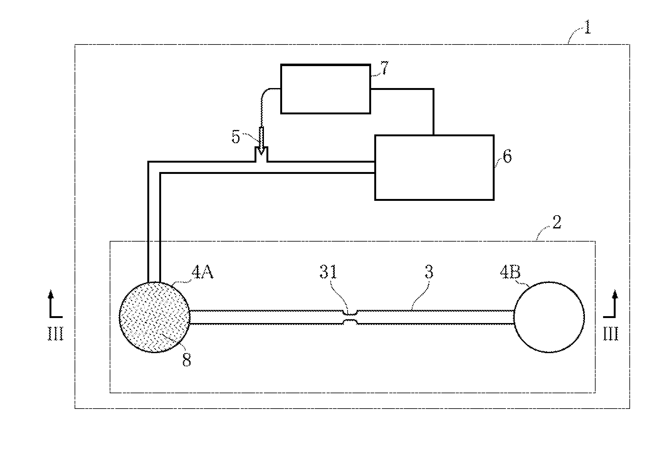
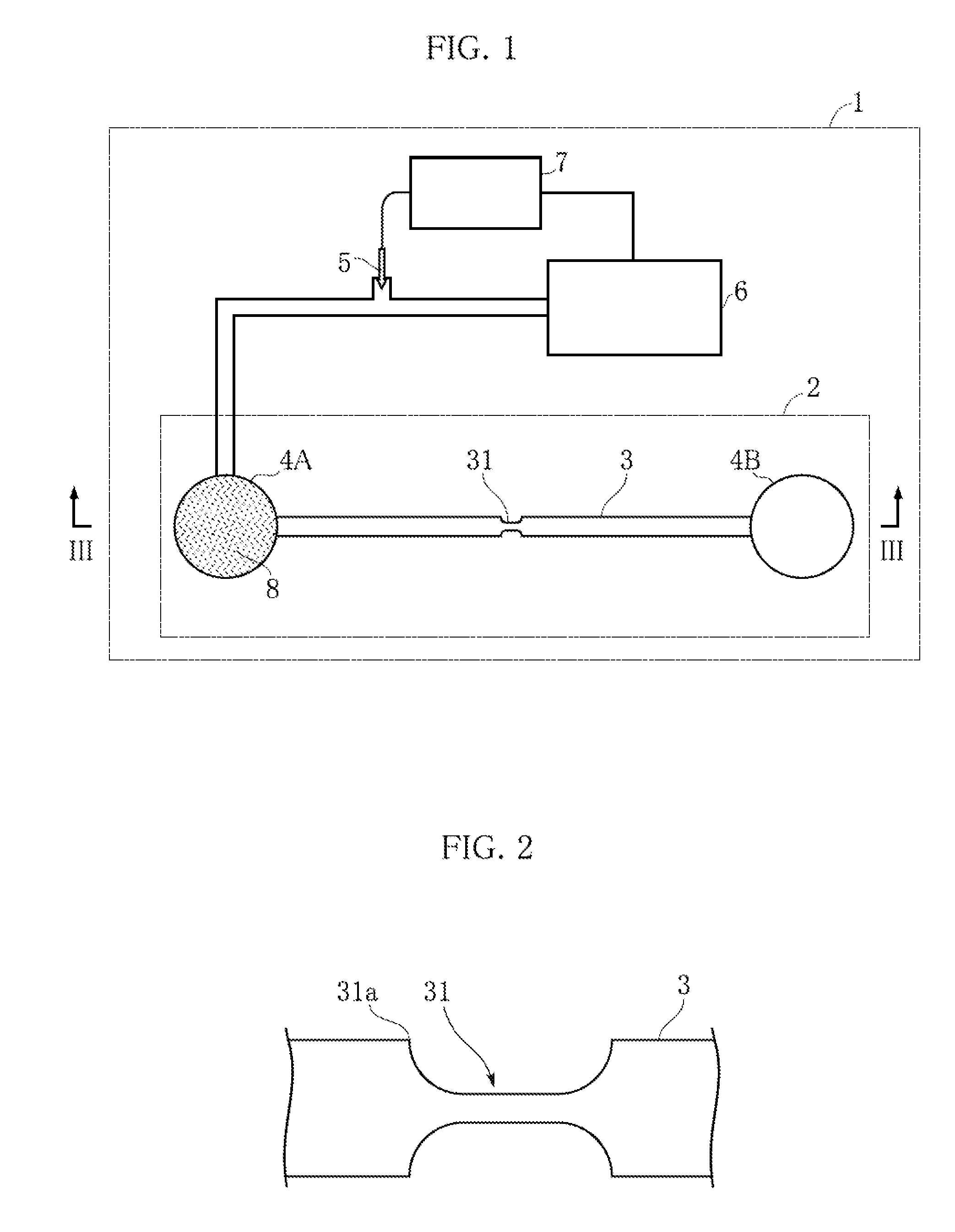
[0035]FIGS. 1 to 3 show an example of a liquid delivery control system according to the present invention. The liquid delivery control system of the present embodiment comprises an analyzer 1 and a cartridge 2. The analyzer 1 and the cartridge 2 use the liquid delivery control method according to the present invention to carry out analyses using an optical method on a specific component such as hemoglobin or C-reactive protein in blood, or to determine blood cell counts such as erythrocyte or leukocyte count.

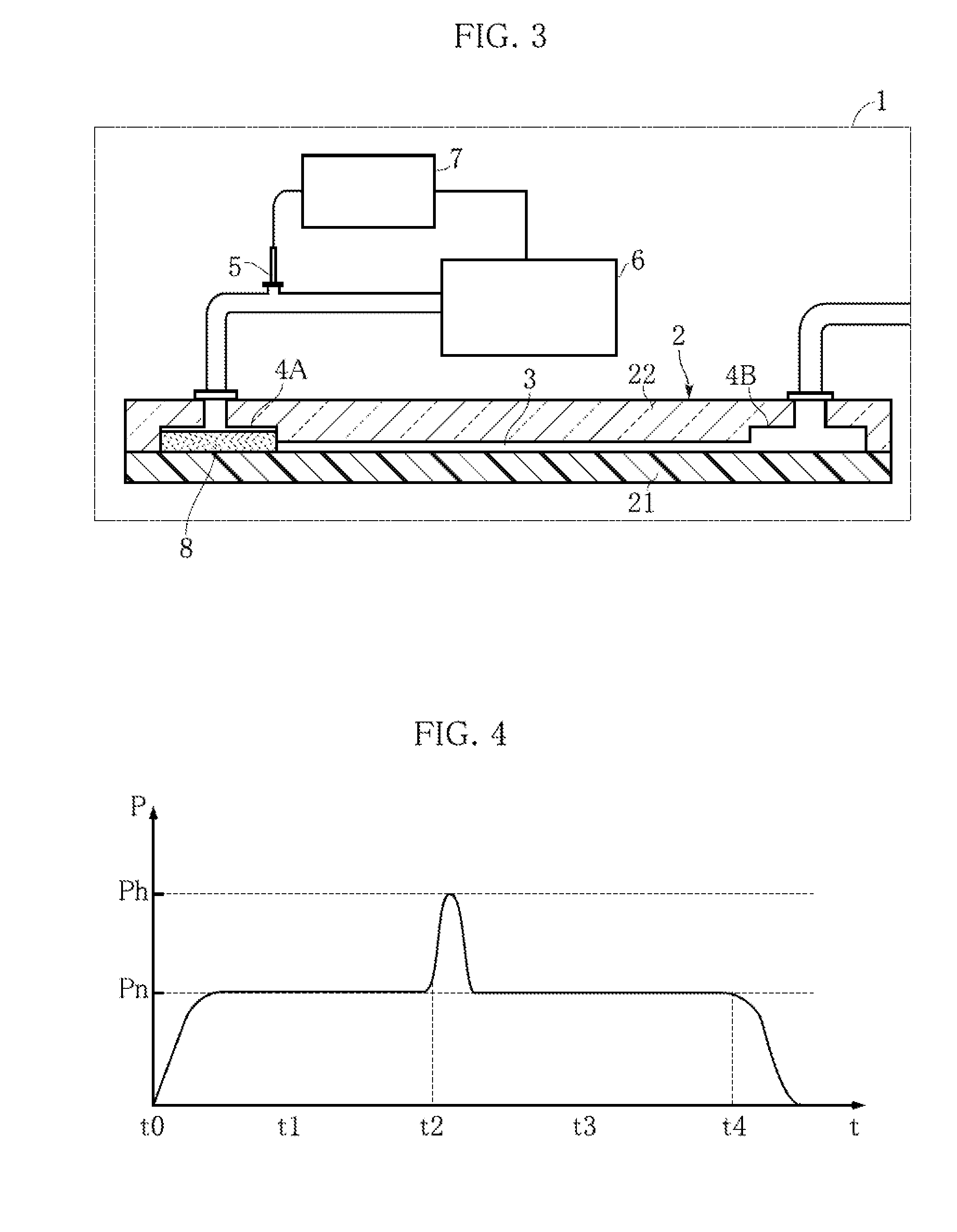
[0036]The analyzer 1 is designed to allow the cartridge 2 to be mounted therein, and includes a pressure sensor 5, a pump 6 and a CPU 7. In addition to these constituents, the analyzer 1 further includes light-emitting means such as an LED module and light-receiving means such as a photodiode for carrying out analyzes using an optical method.

[0037]The pressure sensor 5 is disp...


PUM


Abstract

The present invention provides a liquid delivery control method for delivering a liquid 8 by generating, in a microchannel 3 in which the liquid 8 is present, a differential pressure with respect to the liquid 8 by using a pump 6. The microchannel 3 is provided with a pressure loss varying portion 31 in which pressure loss changes in the direction of flow. The leading end 8a of the liquid 8 is judged to have reached the pressure loss varying portion 31 by detecting a change in pressure between the liquid 8 and the pump 6. With this arrangement, the location of the leading end of the liquid 8 can be properly detected without causing the structure that forms the microchannel 3 to become complex.

Description

TECHNICAL FIELD[0001]The present invention relates to a liquid delivery control method and a liquid delivery control system, which enable the location of the leading end of a liquid delivered in a microchannel to be precisely determined.BACKGROUND ART[0002]Delivery of a liquid in a microchannel is carried out in, for example, a blood analyzer that analyzes a specific component in blood. Blood analyzers dilute specimen blood to a prescribed dilution factor with, for example, a diluent followed by reacting the diluted blood with a reagent and detecting the development of color to analyze the presence and concentration of a specific component. In addition, blood analyzers count the numbers of blood cells such as erythrocytes or leukocytes according to changes in electrical resistance when diluted blood passes over a narrow cross-section. In order to carry out these analyses, it is necessary to deliver fixed amounts of blood, diluent as well as diluted blood from a certain location to a...

Claims


Application Information

Patent Timeline
IPC IPC(8): F15D1/00
CPCB01L3/50273B01L3/502746B01L2200/0642B01L2200/14B01L2300/0816G01N2035/1034B01L2300/14B01L2300/16B01L2400/0415G01N35/1095B01L2300/087Y10T137/0379Y10T137/8593
Inventor HANAFUSA, MASAHIRO
Owner ARKRAY INC
Why Eureka
Try Eureka