Method and apparatus for manufacturing unvulcanized tires

Inactive Publication Date: 2011-01-13
BRIDGESTONE CORP
View PDF3 Cites 11 Cited by
  • Summary
  • Abstract
  • Description
  • Claims
  • Application Information

AI Technical Summary

Benefits of technology

In the invention according to the first, second, fourth and fifth aspects, since the ribbon-like body is supplied from a supply source, it is possible to increase the winding amount of the ribbon-like body, thereby allowing a continuous operation for a long time and improving the work efficiency. Furthermore, upon movement of the winding position of the ribbon-like body, it is possible to suppress unintended movement or deformation of a portion of the ribbon-like body while it is being transferred so as to improve the winding accuracy. Moreover, the moving means and the turning means, which are moved during the winding of the ribbon-like body onto the support member, can be made to have a small weight (light weight), the movement or turning can be performed smoothly to further improve the winding accuracy and achieve an energy saving.
In the above-mentioned aspects of the present invention, when the ribbon-like body is wound helically on the outer surface of the support member, the ribbon-like body has to be supplied substantially along a normal line with respect to the support member, although the ribbon-like body supplied from the supply source travels or extends from the supply source toward the support member. Thus, when the first guide roller is put into a parallel movement along the outer surface of the support member in the meridian direction and turned so that its rotational axis extends in a direction that approaches to a tangent with respect to the outer surface of the support member, the feeding direction of the ribbon-like body must be successively changed following the movement of the winding position or the first guide roller.
To this end, in the invention according to the first and fourth aspects, there is provided a second guide roller arranged on a straight line passing the first guide roller and being perpendicular to a plane including a moving trajectory of the first guide roller. The second guide roller has a rotational axis that extends in a width direction of the ribbon-like body supplied from the supply source to the support member, and is adapted to be moved by the moving means so as to achieve a parallel movement integrally with the first guide roller, so that the ribbon-like body supplied from the supply source is brought into contact successively with the second and first guide rollers, before it is supplied to the outer surface of the support member. Thus, even if the supplying direction of the ribbon-like body from the supply source toward the support member is gradually changed as explained above, the ribbon-like body stretched between the second and the first guide rollers is twisted following the turning of the first guide roller to absorb the change in the supplying direction, thereby allowing the supplying direction of the ribbon-like body to be readily changed accordingly.
Alternatively, in the invention according to the second and fifth aspects, there is provided a second guide roller that arranged on a straight line perpendicular to the rotational axis of the first guide roller, on the side of the first guide roller remote from the support member. The second guide roller has a rotational axis that extends in a width direction of the ribbon-like body supplied from the supply source to the support member, and is to be moved and turned by the moving means and the turning means so as to achieve a parallel movement and a turning movement integrally with the first guide roller, so that the ribbon-like body supplied from the supply source is brought into contact successively with the second and first guide rollers, before it is supplied to the outer surface of the support member. Thus, even if the supplying direction of the ribbon-like body from the supply source toward the support member is gradually changed as explained above, the ribbon-like body stretched between the second and the first guide rollers has a vertical region that achieves a flexural deformation to absorb the change in the supplying direction, thereby allowing the supplying direction of the ribbon-like body to be readily changed accordingly.
Here, upon the helical winding of the ribbon-like body onto the outer surface of the support member, since the first and second guide rollers are driven into a parallel movement along the outer surface of the support member in its meridian direction, the ribbon-like body in contact with the first guide roller is also shifted in the axial direction of the support member following the first guide roller. However, such an axial shifting can be absorbed by a swinging movement of the ribbon-like body between the supply source and the second guide roller, thereby ensuring that the ribbon-like body can be wound onto the outer surface of the support member without any problems.
The arrangement of the present invention according to the sixth aspect is effective even when the ribbon-like body comprises a weak unvulcanized rubber, since it makes possible to positively suppress deformation of the strip member due to lapse of time or under an external force, and also to facilitate handling when it is supplied from the supply source to the support member. Furthermore, the arrangement of the present invention according to the sixth aspect serves to effectively suppress an adverse influence of elongation of the ribbon-like body, which occurs when the strip member is twisted between the first and second guide rollers, since the elongation occurs symmetrically with reference to the widthwise center line passing a center region in a thickness direction of the ribbon-like body.

Problems solved by technology

Thus, due to a limitation in the installation space, it is necessary to restrict the unwinding roll to be small in size and, hence, to suppress the winding amount of the ribbon-like strip to the unwinding roll.
As a result, there is a problem that the unwinding roll has to be exchanged frequently, thereby lowering the working efficiency.
Moreover, because the unwinding roll with a large mass is supported on the turntable, the movement and rotation of the turntable tend to be unstable to degrade the winding accuracy of the ribbon-like body, beside that a large energy is required for the movement and rotation of the turntable.

Method used


Image

  • Method and apparatus for manufacturing unvulcanized tires
  • Method and apparatus for manufacturing unvulcanized tires
  • Method and apparatus for manufacturing unvulcanized tires

Examples


first embodiment

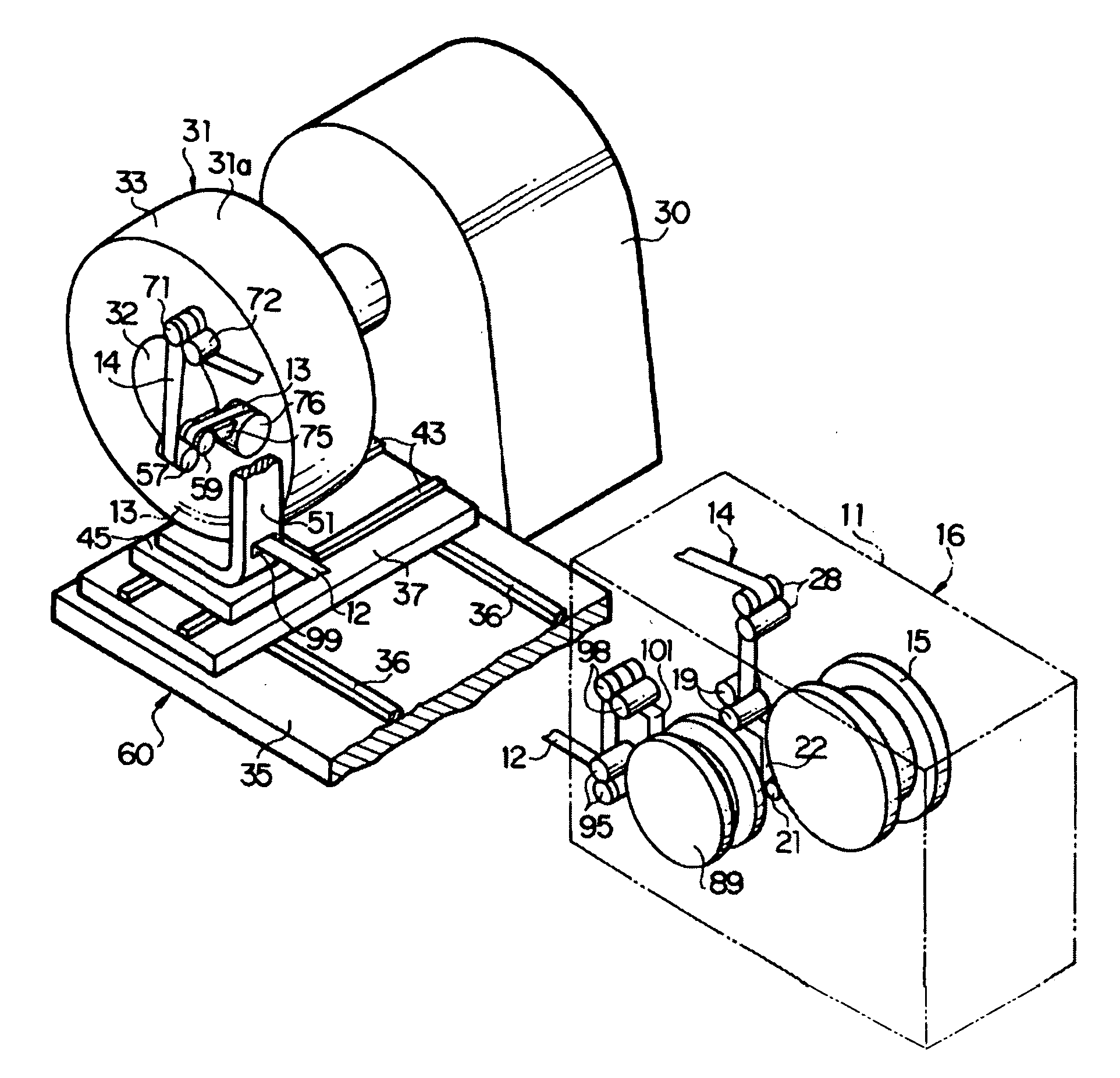
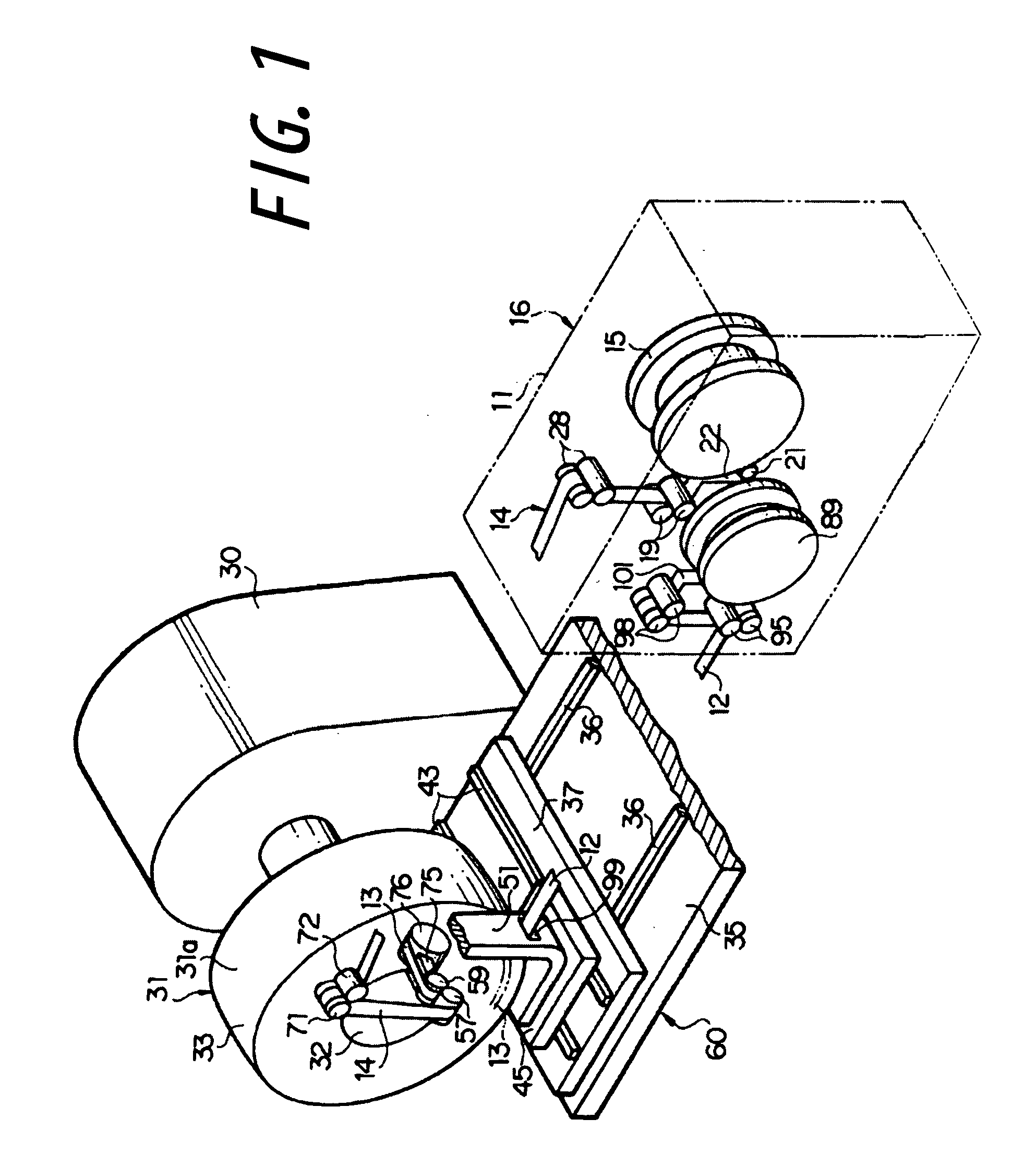
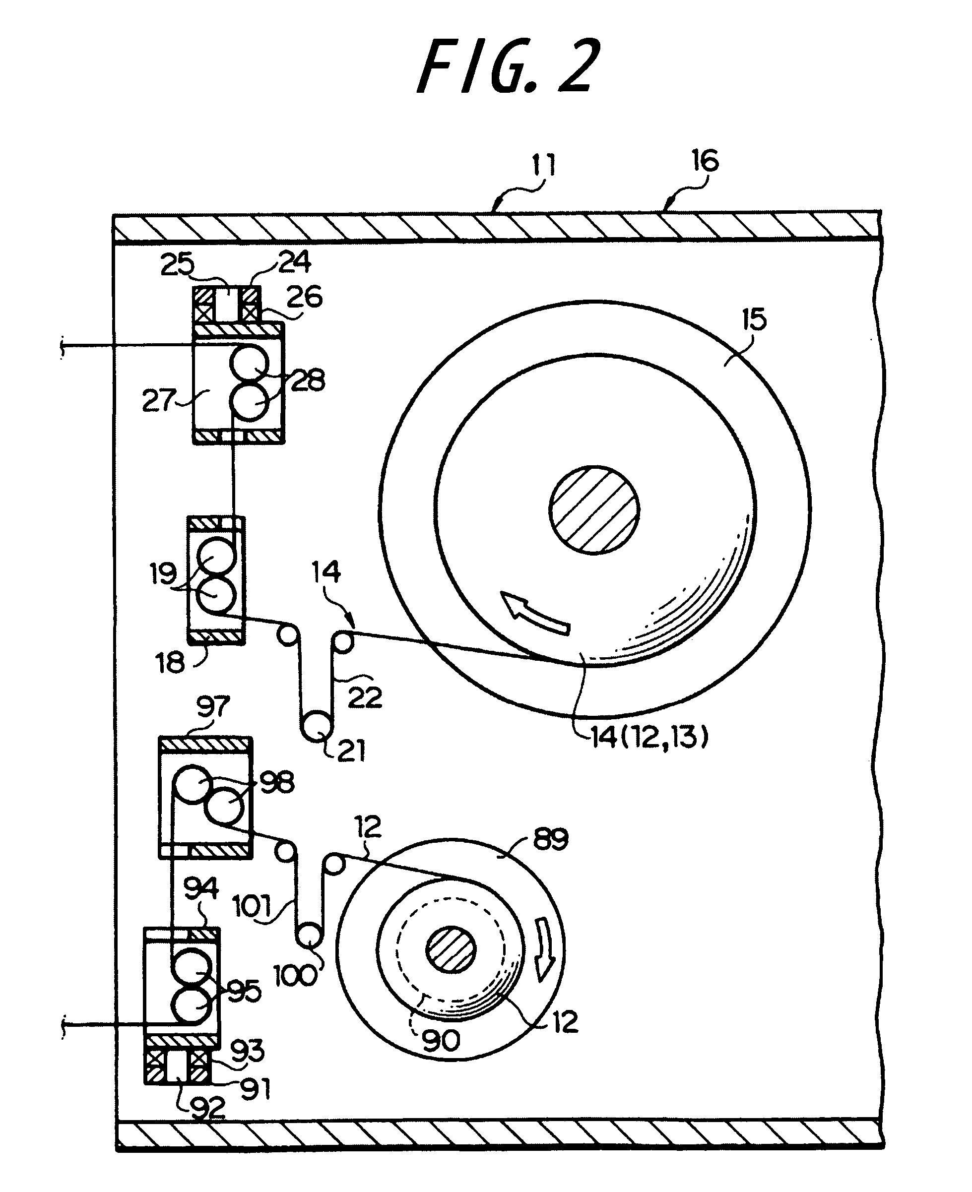
A first embodiment of the present invention will be described below with reference to FIGS. 1 to 4, wherein reference numeral 11 denotes a stationary frame fixedly installed on a floor surface. The stationary frame 11 serves to rotatably support a reel 15, on which a narrow strip member 14 (FIG. 6) comprised of a narrow liner 12 and a narrow ribbon-like body 13 laid over the outer surface side of the liner 12 is wound multiple times. Here, the liner 12 is made of a plastic film, such as a polyethylene film, and the ribbon-like body 13 comprises an unvulcanized rubber. Thus, the liner 12 and the ribbon-like body 13 are wound on the reel 15 as being superimposed with, and adhered to each other under a weak adhesion force.

The reel 15 is normally applied with a slight braking torque. Thus, when the narrow strip member 14 is applied with a predetermined tension and the reel 15 is thereby applied with a resultant torque that exceeds the braking torque, the narrow strip member 14 comprised...

second embodiment

A second embodiment of the present invention is shown in FIG. 7, which is essentially same as the first embodiment described above, except that the rotational axis of the application roller 105 is arranged on a vertical plane (axial plane) that includes the rotational axis of the support body 31, and the rotational axis of the first guide roller 106 is arranged on a plane that is parallel to this vertical plane. Thus, the application roller 105, the first guide roller 106, the second guide roller 107, etc., are moved by the moving means two-dimensionally in these vertical planes, and driven into a parallel movement in the meridian direction along the outer surface 31a of the support member 31. To this end, it is necessary for the moving means to be able move the first guide roller 106, etc., at least on the left-to-right direction and vertical directions. Also, it is usually necessary for the moving means to be able to move the first guide roller 106, etc., in the fore-and-aft direc...

third embodiment

A third embodiment of the present invention is shown in FIG. 8. In the third embodiment, the rotational axis of the application roller 110 is arranged on a horizontal plane (axial plane) that includes the rotational axis of the support member 31, and the rotational axis of the first guide roller 111 is arranged in a plane that is parallel to this horizontal plane, as in the first embodiment. However, the second guide roller 112 is arranged on a straight line perpendicular to the rotational axis of the first guide roller 111, on the side of the first guide roller 111 remote from the support member 31, so that the rotational axis of the second guide roller 112 extends normally in the vertical direction.

With such an arrangement of the third embodiment, the application roller 110 and the first and second guide rollers 111, 112 are moved by the moving means two-dimensionally along the horizontal plane so that these rollers achieve a parallel movement in the meridian direction along the o...


PUM

PropertyMeasurementUnit
Thicknessaaaaaaaaaa
Tensionaaaaaaaaaa

Abstract

A ribbon-like element supplied from a supply source is wound on the rotating toroidal support member, when a first rotatable guide roller arranged spaced from the outer surface of the support member is moved in parallel with the meridian direction along the outer surface of the support member, and turned so that the direction of its rotational axis approaches a tangent relative to the outer surface of the winding member. A second guide roller is arranged on a straight line perpendicular to a plane containing the moving trajectory of the first guide roller and passing through the first guide roller, and has a rotational axis that extends in the widthwise direction of the ribbon-like body extending from the supply source toward the winding member. When the second guide roller is driven to achieve a parallel movement integrally with the first guide roller, the ribbon-like element contacts successively with the second and first guide rollers in this sequence, before it is supplied to the outer surface of the support member.

Description

TECHNICAL FIELDThe present invention relates to a method and an apparatus for manufacturing unvulcanized tires, wherein a ribbon-like body is supplied to an outer surface of a toroidal support member and helically wound thereon multiple times.BACKGROUND ARTThis type of method and apparatus for winding a strip member are generally known in the art, as exemplified, for instance, by Patent Document 1.[Patent Document 1] JP 11-077849AThe apparatus for winding a ribbon-like body as disclosed in Patent Document 1 serves to supply the strip member to an outer surface of a toroidal support member, for helically winding it thereon multiple times, and comprises a first movable table that is movable linearly in one direction, in a first plane including a rotational axis of the support, a first moving means for moving the first movable table in said one direction, a second movable table supported by the first movable table and being movable linearly in a direction perpendicular to said one dire...

Claims


Application Information

Patent Timeline
IPC IPC(8): B29D30/60
CPCB29D30/1628B29D30/3028B29D30/3021
Inventor OGAWA, YUICHIRO
Owner BRIDGESTONE CORP
Why Eureka
Try Eureka