

Fluid-filled type vibration damping device
a technology of vibration damping device and fluid filling, which is applied in the direction of shock absorbers, machine supports, mechanical equipment, etc., can solve the problems of reducing the effect of vibration damping ability, and reducing the effect of vibration damping
- Summary
- Abstract
- Description
- Claims
- Application Information
AI Technical Summary
Benefits of technology
Problems solved by technology
Method used
Image

Examples
first embodiment
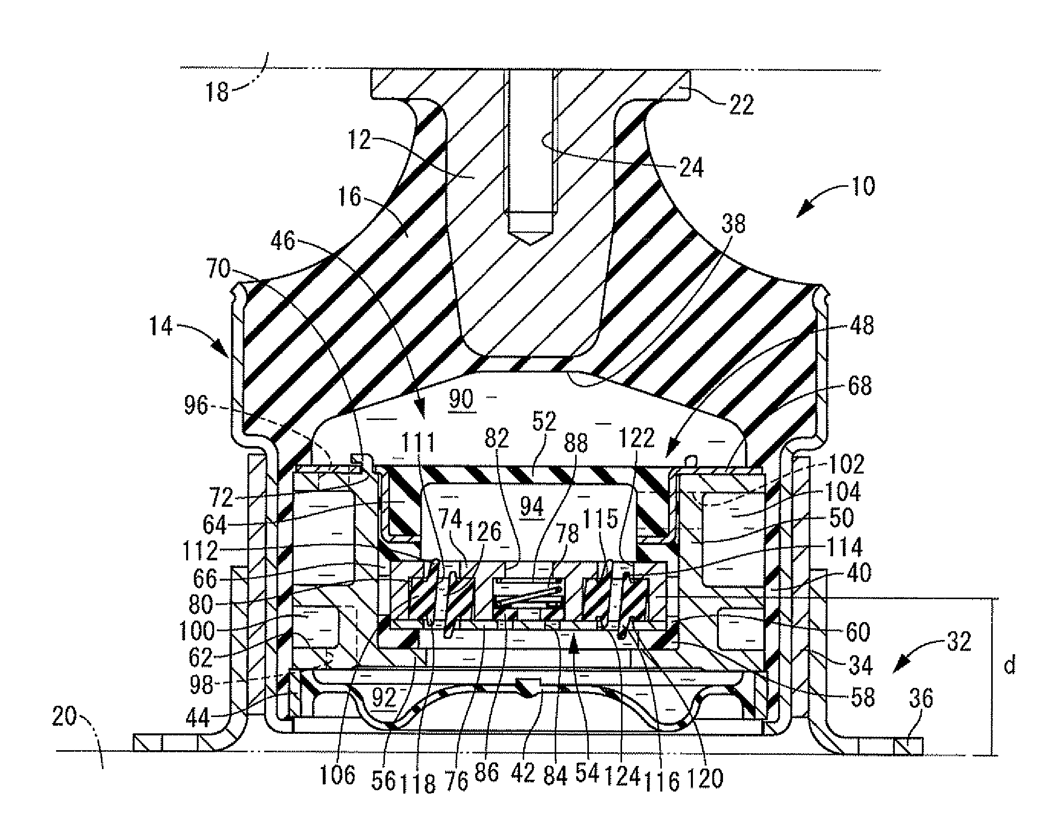
[0043]The embodiments of the present invention are described below with reference to the accompanying drawings. Referring first to FIG. 1, there is depicted an automotive engine mount 10 as the fluid-filled type vibration damping device constructed according to the present invention. The automotive engine mount 10 has a construction in which a first mounting member 12 and a second mounting member 14 are linked to one another by a main rubber elastic body 16. The first mounting member 12 is attached to a power unit 18, while the second mounting member 14 is attached to the vehicle body 20, thereby providing vibration-damped linkage of the power unit 18 to the vehicle body 20. In the following description, as a general rule, the vertical direction refers to the axial direction, which is the vertical direction in FIG. 1.
[0044]Turning to a more detailed discussion, the first mounting member 12 is a high rigidity component made of metal or the like having generally circular post shape. A...
third embodiment
[0116]Next, FIG. 5 depicts an automotive engine mount 156 according to the fluid-filled type vibration damping device constructed according to the invention. The automotive engine mount 156 has a partition member 158, and the partition member 158 includes a partition member body 160 and a receptacle member 162.
[0117]The partition member body 160 is generally circular disk shaped overall, and has a circular center recess 164 that opens onto the bottom face. In the outside peripheral section of the partition member body 160 there is formed a circumferential groove 166 opening onto its outside peripheral face while extending for a prescribed length in the circumferential direction.
[0118]The circular disk-shaped receptacle member 162 is installed in the center recess 164 of the partition member body 160. A pair of receptacle recesses are formed in the outside peripheral section of this receptacle member 162 in areas thereof situated in opposition along a diametrical axis, and open onto ...
fifth embodiment
[0151]In yet another exemplary arrangement, a valve-like rubber projection that projects towards the pressure-receiving chamber 90 side from the rim of the opening of the circular hole 186 is anchored directly onto the upper face of the partition member 184 shown in the fifth embodiment, so that the circular hole 186 becomes blocked through elastic deformation of the valve-like rubber projection.
[0152]In the preceding first to fourth embodiments, the communication holes are communication holes that extend in a straight line; however, communication holes that curve in the circumferential direction or communication holes that follow a sinuous path may be adopted as well. While the communication holes herein are inclined with respect to the axial direction, such incline is not essential.
[0153]In the preceding first to fourth embodiments, a valve-like rubber projection (valve body) is situated to only one side of the communication hole; however, valve-like rubber projections could be fo...
PUM
 Abstract
Description
Claims
Application Information