Method and system for administering remote area monitoring system

a remote area monitoring and monitoring system technology, applied in the field of methods and systems for remotely monitoring an area of interest, can solve the problems of huge time and money costs to the airport, the airlines, passengers, security guards or monitors, regardless, and achieve the effect of reducing workload and ensuring customization

Active Publication Date: 2011-01-13
TEN4WARD +1
View PDF6 Cites 48 Cited by
  • Summary
  • Abstract
  • Description
  • Claims
  • Application Information

AI Technical Summary

Benefits of technology

[0012]The RAMS is readily customized so that the same platform can be used in a wide variety of installations. Once in operation, the system reduces the workload otherwise imposed on security or monitoring personnel while insuring that area security is constantly maintained.

Problems solved by technology

Nonetheless, these are areas of high traffic volume with large groups of people going in one direction to reach a gate, and in the opposite direction to retrieve their luggage, access parking or ground transportation, etc.
While guards are usually effective, there are, nevertheless, numerous instances of security breaches in which someone has gotten past the guard and escaped into the secure area.
As a result, numerous flights are delayed, all at an enormous cost in time and money to the airport, the airlines, and the passengers.
Studies have shown that security guards or monitors, regardless of how dedicated, do not provide the vigilance that is required for prolonged periods of time.
After a while, they become tired and can be distracted.
A drawback with conventional analysis is that it looks for movement only in one direction through the passage.

Method used


Image

  • Method and system for administering remote area monitoring system
  • Method and system for administering remote area monitoring system
  • Method and system for administering remote area monitoring system

Examples


Embodiment Construction

[0037]In the following description, numerous specific details are set forth in order to provide a more thorough description of the present invention. It will be apparent, however, to one skilled in the art, that the present invention may be practiced without these specific details. In other instances, well-known features have not been described in detail so as not to obscure the invention.

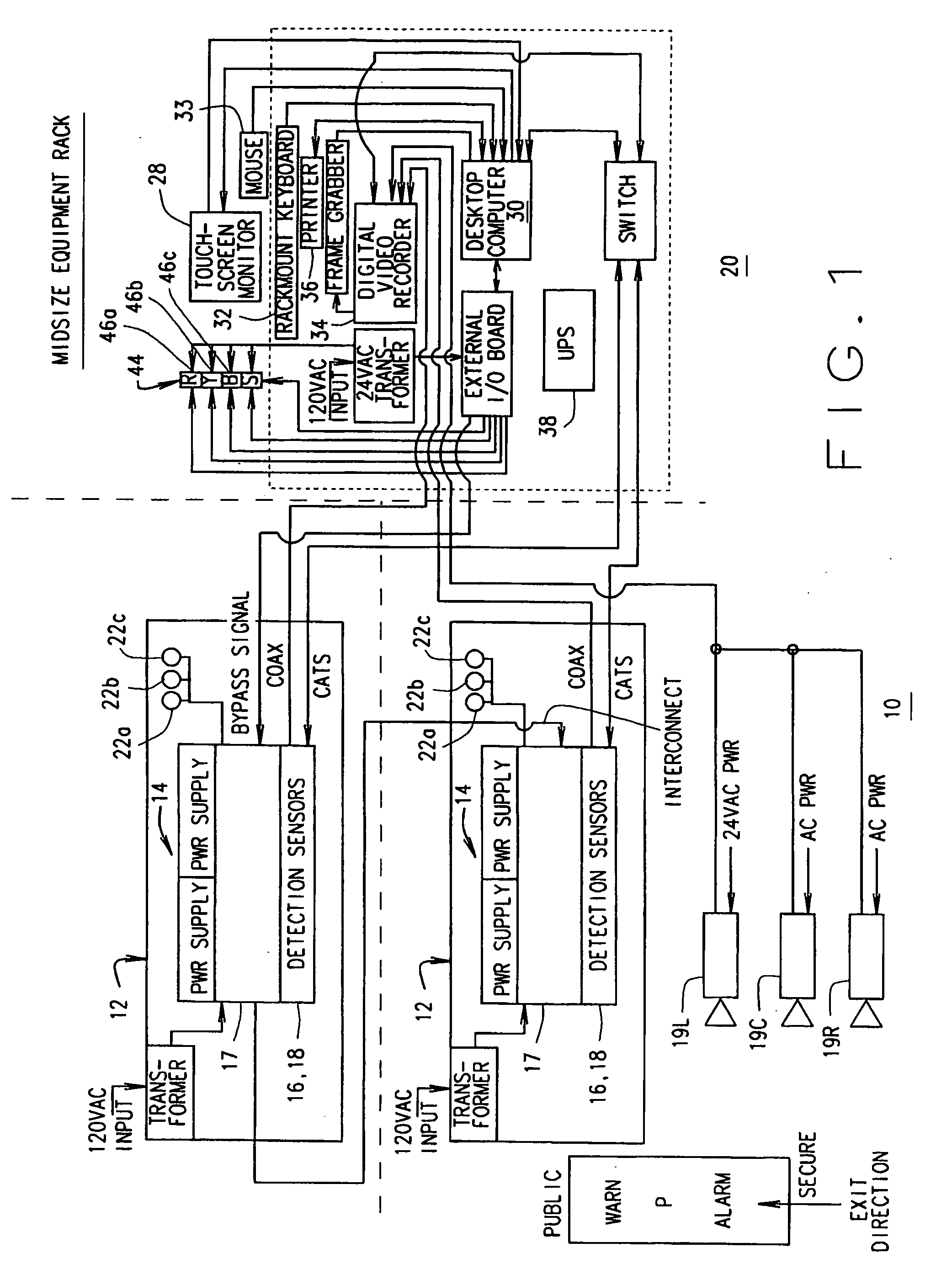
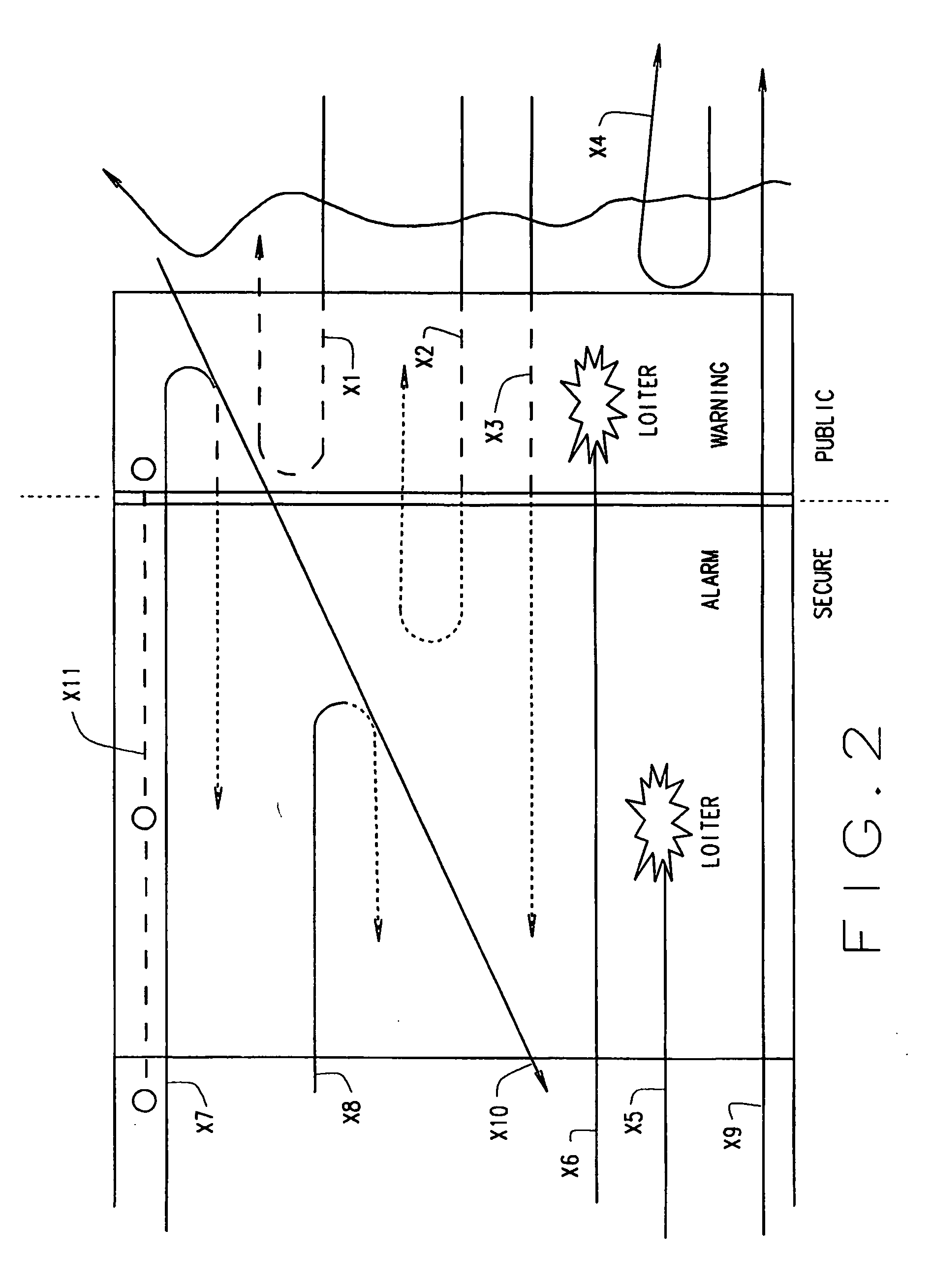
[0038]One embodiment of the invention is a remote area monitoring system (hereinafter “RAMS”), as indicated generally 10 in FIG. 1. The RAMS includes an overhead module 12 in which is mounted a sensor suite 14 that monitors a volumetric area defined in depth, width, and height. As shown in FIG. 1, this area includes both a warning zone and an alarm zone. RAMS 10 automatically monitors the activities in a pedestrian passageway P for wrong-way travel into a secured area; this being done without impeding exit traffic flow. Using advanced machine vision sensing technologies as described hereinafter, RA...


PUM


Abstract

A remote area monitoring system is configured to detect movement in a disallowed direction through a space. The system monitors two volumetric spaces that are established by the system, both of which spaces are defined with respect to depth, width and height. In one embodiment, the system includes one or more stereoscopic sensors for capturing image information of the space, a processor processing the image information to detect movement of humans or objects in a disallowed direction through the space, and an alarm indicator. The system may also include workstation configured to display and store the image information. The workstation may have multiple levels of access, such as basic user, supervisor and technician level access. The workstation may display a log of alarm or related events and permit selection of events and viewing of image information associated with the events.

Description

RELATED APPLICATION DATA[0001]This application is a continuation-in-part of U.S. application Ser. No. 12 / 131,615, filed Jun. 2, 2008, which claims priority to U.S. Provisional Patent Application Ser. No. 60 / 942,872, filed June 8, 2007.FIELD OF THE INVENTION[0002]This invention relates to a method and apparatus for remotely monitoring an area of interest; for example, a pedestrian passageway such the entrance into, and exit from, a concourse in an airport terminal; and more particularly, to detecting a security breach resulting from inadvertent or intentional wrong way travel of people and objects through an exit passageway and to provide an immediate and specific indication thereof.BACKGROUND OF THE INVENTION[0003]For some time now, airport concourses have been secured areas to which only authorized individuals (employees or screened passengers) are permitted access. Nonetheless, these are areas of high traffic volume with large groups of people going in one direction to reach a gat...

Claims


Application Information

Patent Timeline
Patent Type & Authority Applications(United States)
IPC IPC(8): H04N15/00G08B13/00
CPCG08B13/19669G08B13/19613
Inventor BRUNETTI, SAM F.
Owner TEN4WARD
Why Eureka
Try Eureka