Lighting device, display device and television receiver

a technology of display device and light fixture, which is applied in the direction of lighting support device, television system, instruments, etc., can solve the problems of chassis distortion, small height from the bottom plate to the upper edge of the outer rim, and reduce so as to suppress the chassis distortion, improve the strength of the outer rim, and improve the strength of the whole chassis

Active Publication Date: 2011-01-13
SHARP KK
View PDF4 Cites 16 Cited by
  • Summary
  • Abstract
  • Description
  • Claims
  • Application Information

AI Technical Summary

Benefits of technology

[0009]A double folding configuration having the first folded portion and the second folded portion that is formed by further folding a part of the first folded portion is provided at the outer rim that is formed at the edge of the bottom plate of the chassis. This improves strength of the outer rim and suppresses distortion of the whole chassis.
[0010]The outer rim having the folding configuration that is provided at the edge of the bottom plate of the chassis has a function for applying strength that is required to suppress the distortion of the chassis of a plate shape. However, especially in the thin chassis, a height from the bottom plate to an upper edge of the outer rim is small. Therefore, the strength of the outer rim is decreased compared to the conventional chassis. This decreases the strength of the whole chassis and may cause distortion of the chassis.
[0011]If the distortion is caused in the chassis, a distance between each light source accommodated in the chassis and the chassis may be varied. If the chassis is made of a metal, a small amount of leakage is caused from the light source and the leakage amount is inversely proportional to the distance between the light source and the chassis. Therefore, if the distance between each light source and the chassis is different due to the distortion of the chassis, the leakage amount from each light source is varied. In a case in that a large distance between the light sources and the chassis can be ensured, even if the distance therebetween is changed due to the distortion of the chassis, the variation of the leakage amount in the light sources is small since the distance change amount with respect to the design distance is relatively small. Accordingly, this does not affect the variation of current flowing in the light sources. However, since the distance between the light sources and the chassis is small in the thin chassis, the distance change amount with respect to the design distance is relatively great. As a result, this increases the variation of current flowing in the light sources, and accordingly the brightness of each light source may be different.
[0012]However, in the lighting device of the present invention, the outer rim has a folding configuration comprising the first folded portion and the second folded portion that is formed by folding the plate member that forms the first folded portion. This improves the strength of the whole chassis and does not cause distortion in the thin chassis. Accordingly, since the distance between the light sources and the chassis is maintained to be the design distance, the leakage amount from each light source to the chassis is constant and this does not affect the variation of current flowing in the light sources, that is, the variation of brightness. As a result, especially in the thin lighting device, a uniform light brightness distribution is ensured.

Problems solved by technology

However, especially in the thin chassis, a height from the bottom plate to an upper edge of the outer rim is small.
This decreases the strength of the whole chassis and may cause distortion of the chassis.

Method used


Image

  • Lighting device, display device and television receiver
  • Lighting device, display device and television receiver
  • Lighting device, display device and television receiver

Examples


first embodiment

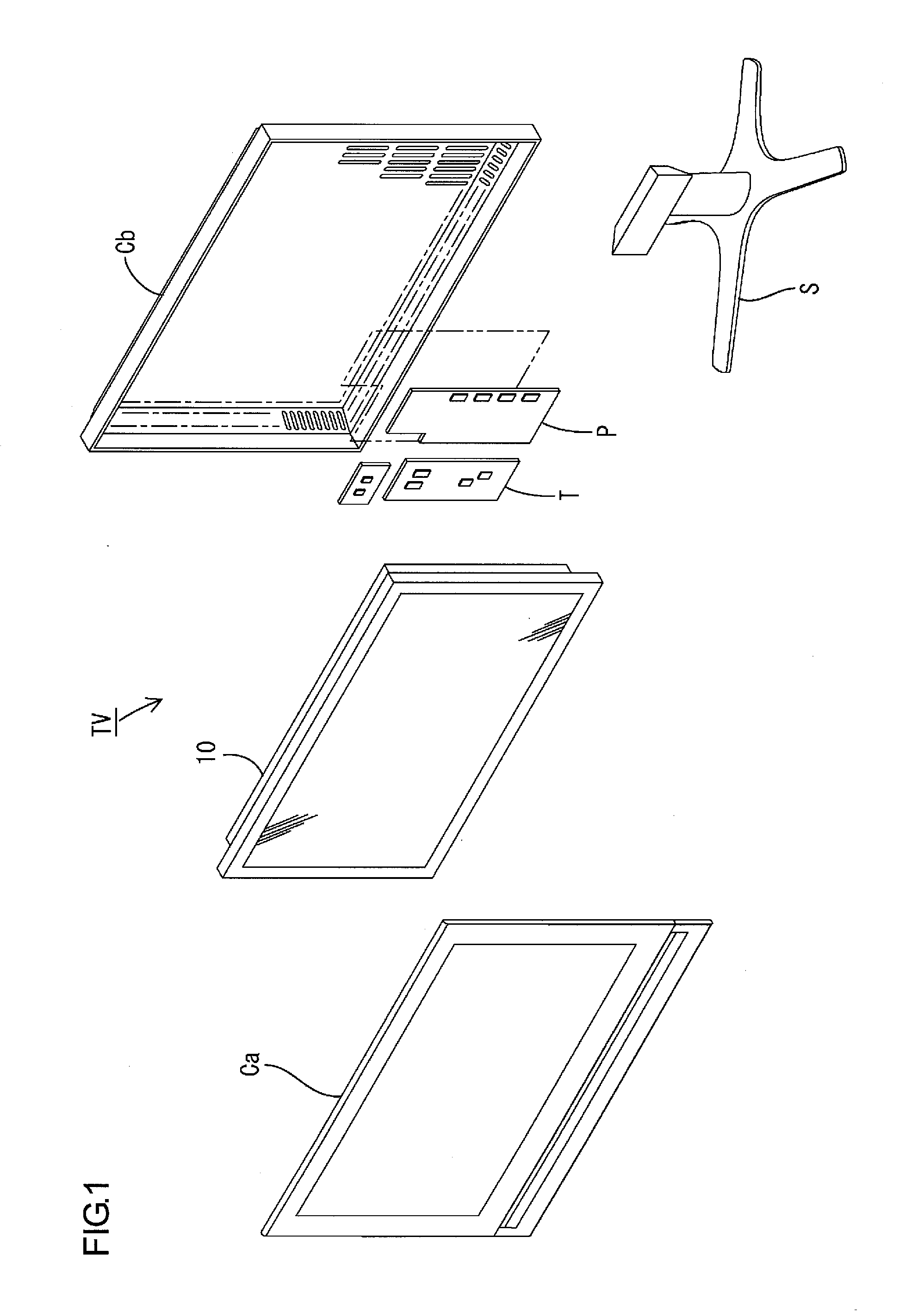
[0037]The first embodiment of the present invention will be explained with reference to FIGS. 1 to 6. In the first embodiment, a television receiver TV including a liquid crystal display device 10 will be explained.

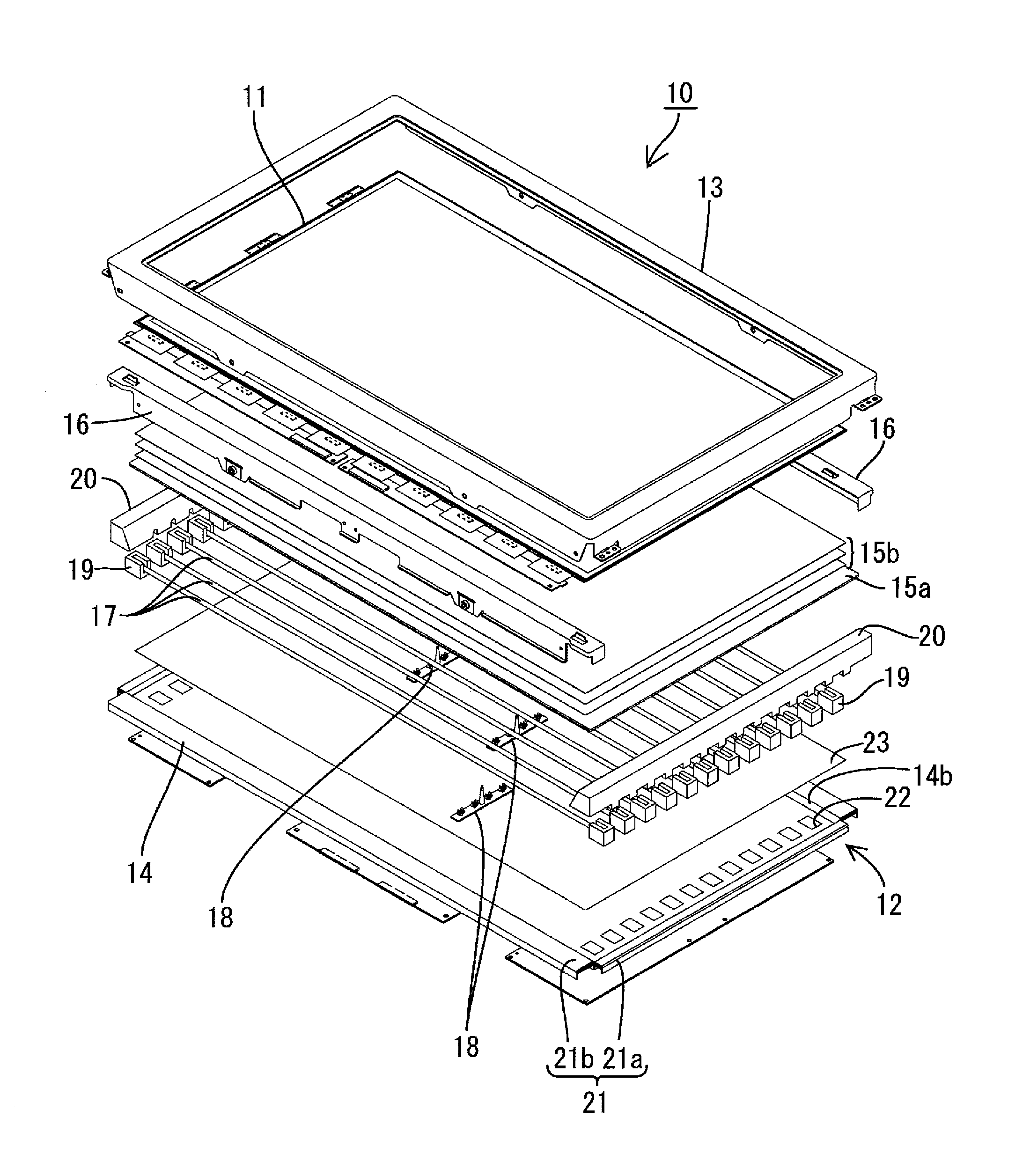
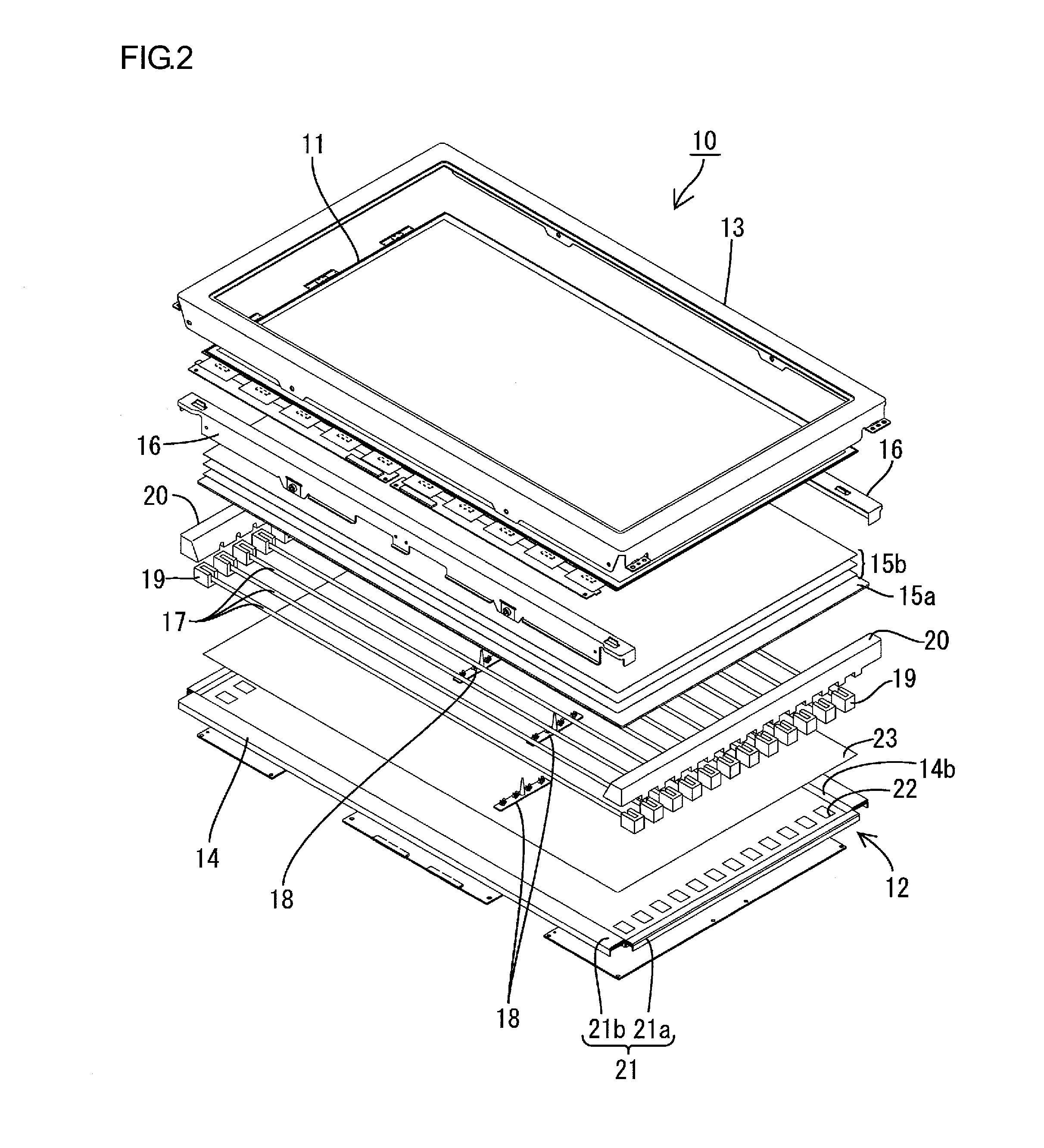
[0038]FIG. 1 is an exploded perspective view illustrating a general construction of the television receiver according to the first embodiment. FIG. 2 is an exploded perspective view illustrating a general construction of the liquid crystal display device provided in the television receiver shown in FIG. 1. FIG. 3 is a cross-sectional view of the liquid crystal display device in FIG. 2 along the short-side direction. FIG. 4 is a cross-sectional view of the liquid crystal display device in FIG. 2 along the long-side direction. FIG. 5 is an enlarged cross-sectional view of a main portion of the liquid crystal display device in FIG. 3. FIG. 6 is an enlarged cross-sectional view of a main portion of the liquid crystal display device in FIG. 4.

[0039]As illustrated in FIG. 1, th...

second embodiment

[0079]Next, a second embodiment of the present invention will be explained with reference to FIGS. 13 to 15. In the second embodiment, a reinforcing plate is provided in the folded part of the outer rim, and other configurations are same as the above embodiment. The same parts as the above embodiment are indicated by the same symbols and the explanation thereof is omitted.

[0080]FIG. 13 is an enlarged cross-sectional view illustrating a cross-sectional configuration of a main portion along a short-side direction of the liquid crystal display device according to the second embodiment. FIG. 14 is an enlarged cross-sectional view illustrating a cross-sectional configuration of a main portion along a long-side direction of the liquid crystal display device. FIG. 15 is a perspective view illustrating a configuration of a reinforcing plate attached to the folded outer rim in the liquid crystal display.

[0081]The chassis 14 is formed in a substantially shallow box shape with plating. It incl...


PUM

PropertyMeasurementUnit
distanceaaaaaaaaaa
heightaaaaaaaaaa
diameteraaaaaaaaaa

Abstract

A lighting device 12 of the present invention includes a plurality of light sources 17 and a chassis 14 that accommodates the light sources 17. The chassis 14 is formed of a plate member and includes a bottom plate 14a of a flat plate and outer rims 21 having a folding configuration formed at the edges of the bottom plate 14a. The outer rim 21 includes a first folded portion 31 and a second folded portion 32 that is formed by further folding a part of the first folded portion 31. Since the outer rim 21 has a double folding configuration, strength of the outer rim 21 itself is increased to suppress distortion of the chassis 14. Accordingly, uniform brightness is provided.

Description

TECHNICAL FIELD[0001]The present invention relates to a lighting device, a display device and a television receiver.BACKGROUND ART[0002]A liquid crystal panel included in a liquid crystal display device such as a television does not emit light, and thus a backlight device is required as a separate lighting device. The backlight device is arranged behind the liquid crystal panel (i.e., on a side opposite from a display surface side). It includes a metal chassis having an opening on a liquid crystal panel side and a plurality of lamps (e.g., cold cathode tubes).[0003]To make the liquid crystal display device thinner and lighter, each component of the liquid crystal panel and the backlight device has been made thinner and lighter. The reduction in thickness and weight of the components decreases strength of the components and accordingly lowers durability or display quality of the liquid crystal display device. To suppress the strength decrease of the components due to the weight reduc...

Claims


Application Information

Patent Timeline
Patent Type & Authority Applications(United States)
IPC IPC(8): H04N5/64F21S4/00G02F1/13357G02F1/1335
CPCG02F1/133608G02F1/133604
Inventor YAMAMOTO, SHUKISATOH, TAMOTSU
Owner SHARP KK
Why Eureka
Try Eureka