Acoustic signal processing device and acoustic signal processing method

a signal processing and acoustic signal technology, applied in the direction of stereophonic system, stereophonic arrangment, electrical apparatus, etc., can solve the problems of multi-channel surround sound format, inability to arrange a plurality of speakers in the recommended symmetrical position, etc., to suppress the occurrence of discomfort

Inactive Publication Date: 2011-01-13
PIONEER CORP
View PDF0 Cites 126 Cited by
  • Summary
  • Abstract
  • Description
  • Claims
  • Application Information

AI Technical Summary

Benefits of technology

[0007]The technique of the prior art example described above is a technique for suppressing the occurrence of a sense of discomfort in the user with respect to audio volume, due to changeover of the sound source device. Due to this, the technique of the prior art example is not one in which sound field correction processing is performed for making it appear that the sound field created by output audio from a plurality of speakers is brimming over with realism.

Problems solved by technology

Because of this, quite often circumstances occur in which it is not possible to arrange a plurality of speakers that output audio in positions which are symmetrical from the standpoint of the multi-channel surround sound format.
In particular, if an audio device that employs the multi-channel surround sound format is to be installed in a vehicle, due to constraints upon the sitting positions which are also the listening positions, it is not possible to arrange a plurality of speakers in the symmetrical positions that are recommended from the standpoint of the multi-channel surround sound format.
Furthermore, when the multi-channel surround sound format is implemented, it is often the case that the characteristics of the speakers are not optimal.

Method used


Image

  • Acoustic signal processing device and acoustic signal processing method
  • Acoustic signal processing device and acoustic signal processing method
  • Acoustic signal processing device and acoustic signal processing method

Examples


first embodiment

The First Embodiment

[0043]First, the first embodiment of the present invention will be explained with reference to FIGS. 1 through 14.

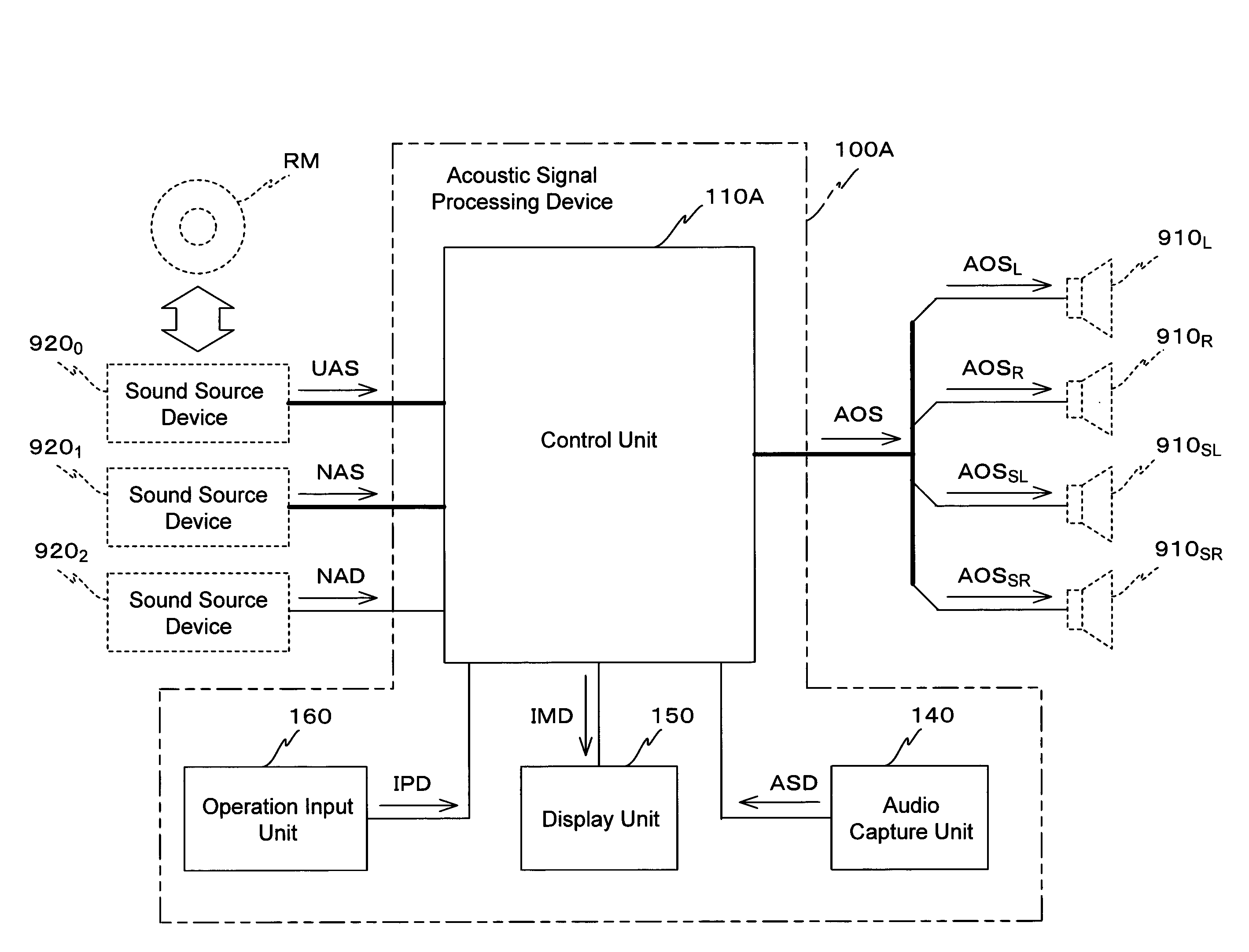
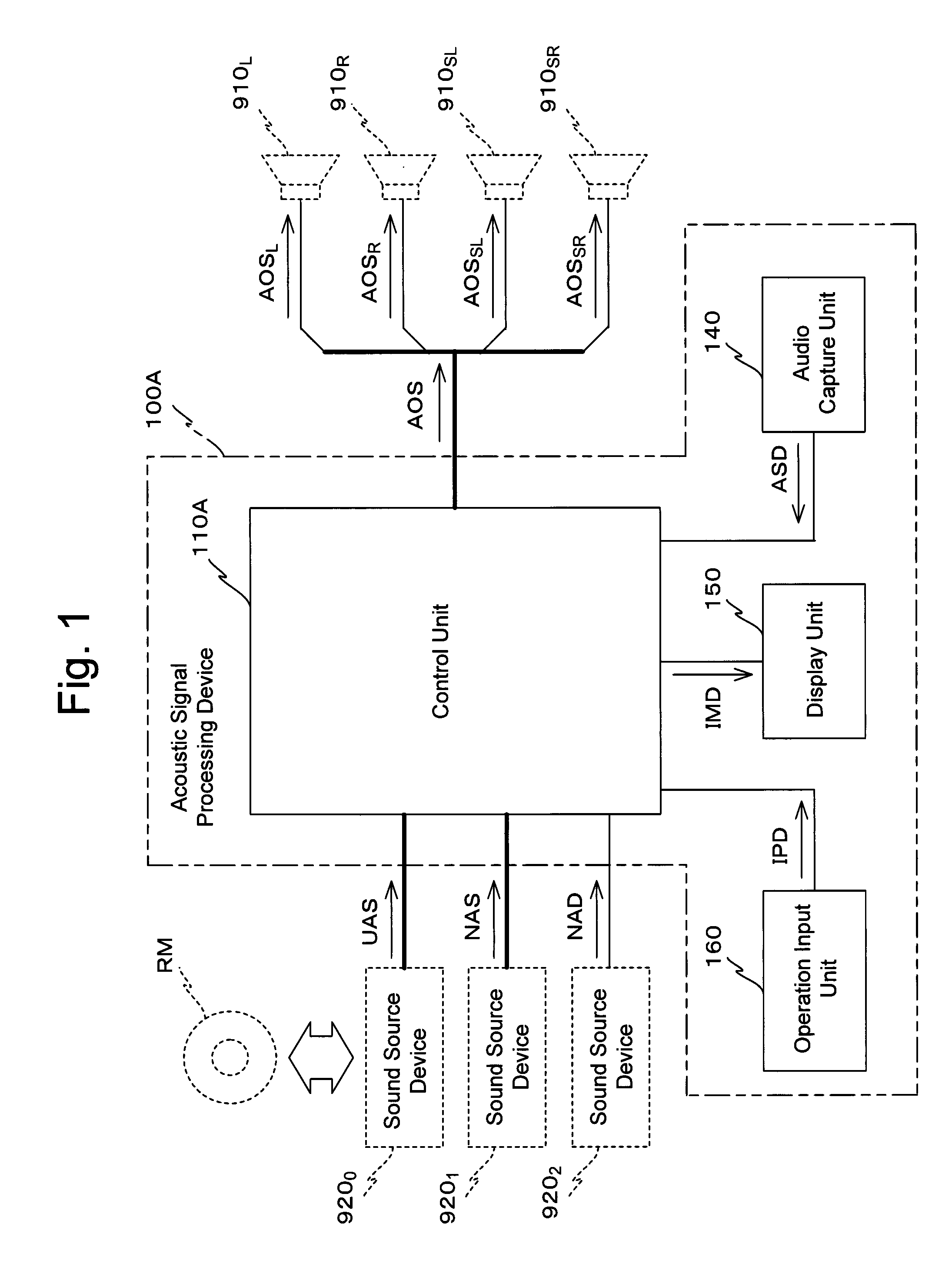
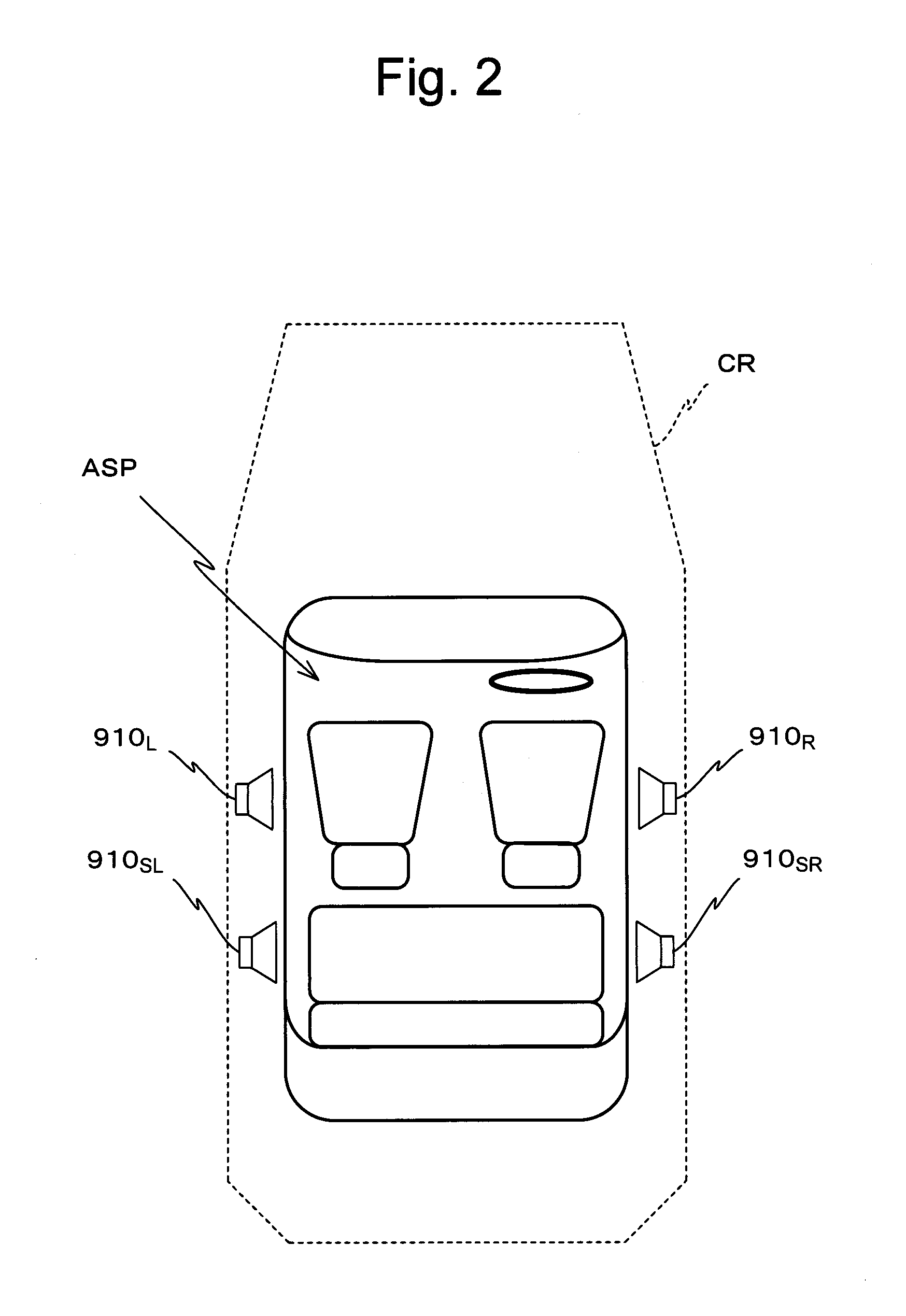
[0044]In FIG. 1, the schematic structure of an acoustic signal processing device 100A according to the first embodiment is shown as a block diagram. It should be understood that, in the following explanation, it will be supposed that this acoustic signal processing device 100A is a device that is mounted to a vehicle CR (refer to FIG. 2). Moreover, it will be supposed that this acoustic signal processing device 100A performs processing upon an acoustic signal of the four channel surround sound format, which is one multi-channel surround sound format. It will be supposed that by an acoustic signal of the four channel surround sound format, is meant an acoustic signal having a four channel structure and including a left channel (hereinafter termed the “L channel”), a right channel (hereinafter termed the “R channel”), a surround left channel (hereinafte...

second embodiment

The Second Embodiment

[0135]Next, the second embodiment of the present invention will be explained with principal reference to FIGS. 15 through 22.

[0136]The schematic structure of an acoustic signal processing device 100B according to the second embodiment is shown in FIG. 15. As shown in this FIG. 15, as compared to the acoustic signal processing device 100A of the first embodiment described above (refer to FIG. 1), this acoustic signal processing device 100B only differs by the feature that a control unit 110B is provided, instead of the control unit 110A. And, as shown in FIG. 16, as compared with the control unit 110A described above (refer to FIG. 3), this control unit 110B only differs by the features that an output audio data generation part 114B is provided, instead of the output audio data generation part 114A, and that a processing control part 119B is provided, instead of the processing control part 119A.

[0137]As compared to the output audio data generation part 114A descr...

third embodiment

The Third Embodiment

[0175]Next, the third embodiment of the present invention will be explained with principal reference to FIGS. 23 through 27.

[0176]The schematic structure of an acoustic signal processing device 100C according to the third embodiment is shown in FIG. 23. As shown in this FIG. 23, as compared to the acoustic signal processing device 100B of the second embodiment described above (refer to FIG. 15), this acoustic signal processing device 100C only differs by the feature that a control unit 110C is provided, instead of the control unit 110B. As shown in FIG. 24, as compared with the control unit 110B described above (refer to FIG. 16), this control unit 110C only differs by the features that an output audio data generation part 114C is provided, instead of the output audio data generation part 114B, and that a processing control part 119C is provided, instead of the processing control part 119B.

[0177]As compared to the output audio data generation part 114B described ...


PUM


Abstract

A corrective measurement part of a processing control part 119A measures an aspect of specific sound field correction processing performed on an acoustic signal received from a specific external device. Based on this measurement result, settings for cancellation of specific sound field correction processing performed on that acoustic signal are made for a correction cancellation part 310. Furthermore, an aspect of appropriate sound field processing corresponding to the actual sound field space is acquired by an appropriate correction acquisition part of the processing control part 119A. Based on the result acquired in this manner, settings for performing appropriate sound field correction processing upon a signal SND are made for a correction processing part 330. Thus, whichever one of acoustic signals received by a reception processing part 111 is selected, an output acoustic signal can be supplied to speaker units in after appropriate sound field correction processing.

Description

TECHNICAL FIELD[0001]The present invention relates to an acoustic signal processing device, to an acoustic signal processing method, to an acoustic signal processing program, and to a recording medium upon which that acoustic signal processing program is recorded.BACKGROUND ART[0002]In recent years, along with the widespread use of DVDs (Digital Versatile Disks) and so on, audio devices of the multi-channel surround sound type having a plurality of speakers have also become widespread. Due to this, it has become possible to enjoy surround sound brimming over with realism both in interior household spaces and in interior vehicle spaces.[0003]There are various types of installation environment for audio devices of this type. Because of this, quite often circumstances occur in which it is not possible to arrange a plurality of speakers that output audio in positions which are symmetrical from the standpoint of the multi-channel surround sound format. In particular, if an audio device t...

Claims


Application Information

Patent Timeline
Patent Type & Authority Applications(United States)
IPC IPC(8): H04R5/00
CPCH04R2499/13H04S7/308H04S7/301
Inventor TOMODA, NOBUHIROSUGAWARA, KEITAROYOSHIDA, KENSAKUSANO, TAKAICHIFURUNOBU, MOMOTOSHI
Owner PIONEER CORP
Why Eureka
Try Eureka