Pressure exchanger for transmitting pressure energy from a first liquid stream to a second liquid stream

a pressure exchanger and liquid stream technology, applied in the direction of positive displacement liquid engine, pump components, pump control, etc., can solve the problem of unusable mixing of salt water and brine, and achieve the effect of accurate control or regulation of rotational speed

Active Publication Date: 2011-01-13
GRUNDFOS MANAGEMENT AS
View PDF2 Cites 26 Cited by
  • Summary
  • Abstract
  • Description
  • Claims
  • Application Information

AI Technical Summary

Benefits of technology

[0005]With regard to the above-identified problem, it is the object of the present invention to improve a pressure exchanger in a manner such that an as large as possible efficiency and a reliable operation of the pressure exchanger is simultaneously achieved, and an undesired mixing of the two fluid flows with one another is avoided.
[0011]According to the present invention, a drive motor, preferably an electric drive motor is provided for rotating the rotor. What is essential to the present invention is that setting means are present, by way of which the rotational speed of the rotor may be changed. This may in particular be effected by way of changing the rotational speed of the drive motor. These setting means permit an adaptation of the rotor speed to the current constraints of the installation, in particular to the current volume flow of the first fluid flow and the second fluid flow. The rotational speed of the rotor may thereby be adapted to the volume flows, such that an optimal pressure transmission is effected, without the fluid flows having to mix with one another more than is necessary. On operation of such a pressure exchanger, a mixing zone forms in the channels, in which the two fluid flows come into contact with one another. On exchange of the pressure energy, this mixing zone moves in the channels in the axial direction. In order to avoid a real mixing of the fluid flows between the entry for the first fluid flow and the exit for the second fluid flow, this mixing zone however must advantageously always remain in the inside of the channel. Simultaneously, in order to achieve a high efficiency of the pressure exchanger, the distance by which this mixing zone moves in the axial direction should be as large as possible, preferably correspond to almost the complete length of the channel in the axial direction. The movement of the mixing zone however depends on external parameters, in particular the pressure differences and the volume flows as well as the rotational speed of the rotor. If now, the rotational speed of the rotor may be changed, it is possible to always adapt the rotational speed of the rotor, such that the mixing zone remains in the inside of the channel and the efficiency is simultaneously maximized.
[0012]Preferably a control and regulation (closed-loop control) device is provided, via which the rotational speed of the rotor may be set. This is effected further preferably in an automatic manner, in order to operate the pressure exchanger always with a rotor rotational speed, which permits the maximum efficiency at given volume flows and pressure differences.
[0013]Further preferably, the control or regulation device are designed in a manner such that it sets the rotational speed of the rotor such that a mixing zone, in which a mixing between the first fluid flow and the second fluid flow occurs, is always situated in the inside of the channels. As described, a mixing of the fluid flows is prevented by way of this. Simultaneously, the control or regulation device preferably executes the control or regulation in a manner such that the axial distance by which the mixing zone moves on rotation of the rotor, is maximized. This ensures the highest possible efficiency.
[0019]According to a further preferred embodiment of the present invention, means for detecting the rotational speed of the rotor may be present, in particular a rotational speed sensor may be arranged on the rotor. This permits the current rotational speed to be detected and to be taken into account with the control or and regulation (closed-loop control) of the rotational speed. The control or regulation device may thus obtain a feedback as to how high the actual rotor rotational speed is. Thus, an even more accurate control or regulation of the rotational speed of the drive motor and thus adaptation to the actual operating conditions is possible.

Problems solved by technology

The problem with such prior art pressure exchangers of the construction type which is known from EP 0 298 097 B1, is the fact that any undesirable mixing of salt water and brine may occur in the pressure exchanger, since both fluid flows are not completely separated from one another.

Method used


Image

  • Pressure exchanger for transmitting pressure energy from a first liquid stream to a second liquid stream
  • Pressure exchanger for transmitting pressure energy from a first liquid stream to a second liquid stream
  • Pressure exchanger for transmitting pressure energy from a first liquid stream to a second liquid stream

Examples


Embodiment Construction

[0027]Certain terminology is used in the following description for convenience only and is not limiting. Unless specifically set forth herein, the terms “a,”“an” and “the” are not limited to one element, but instead should be read as meaning “at least one.” The terminology includes the words used herein, derivatives thereof and words of similar import.

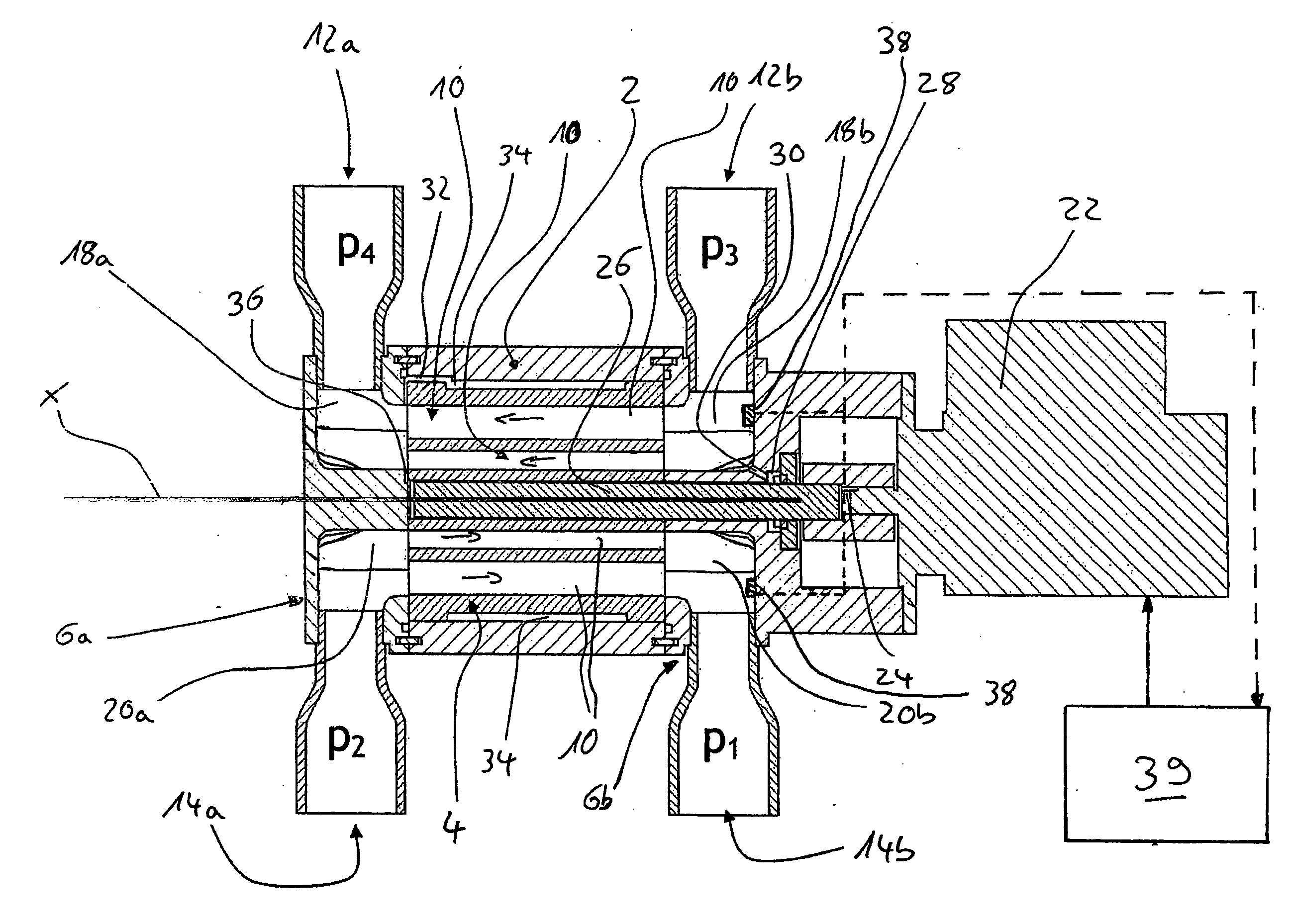
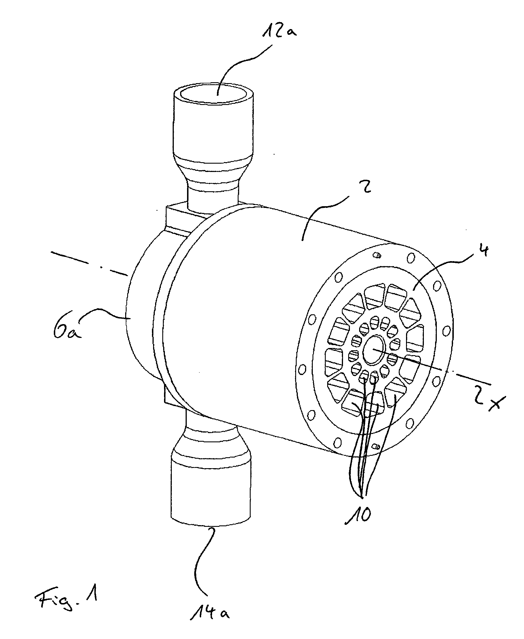
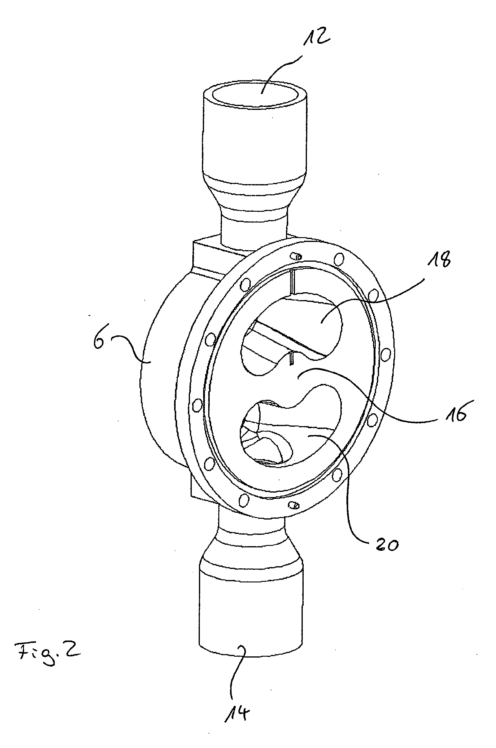
[0028]Referring to the drawings in detail, wherein like numerals indicate like elements throughout the several views, the geometric construction of the pressure exchanger of the present invention corresponds essentially to the pressure exchanger known from EP 0 298 097 B 1. The pressure exchanger of the present invention comprises a cylindrical housing 2, in whose inside a rotor 4 is arranged in a rotatable manner. Thereby, the rotor 4 is rotatable about the longitudinal axis X of the housing 2 and rotor 4. The housing 2 at the two axial sides is closed in each case by a connection element 6. Both connection elements 6 are designed in ...


PUM


Abstract

A pressure exchanger for transmitting pressure energy from a first fluid flow to a second fluid flow includes a housing having an entry and an exit for the first fluid flow and an entry and an exit for the second fluid flow. A rotor arranged in the housing includes a multitude of channels which extend radially distanced to a rotation axis of the rotor. The rotor is arranged to the entries and exits in a manner such that the channels, on rotation of the rotor, in each case in an alternating manner, connect the entry for the first fluid flow to the exit for the second fluid flow, and the entry for the second fluid flow to the exit for the first fluid flow, and with a drive motor via which the rotor may be driven in rotation, and with setting means for changing the rotational speed of the rotor.

Description

CROSS-REFERENCE TO RELATED APPLICATIONS[0001]This application is a Section 371 of International Application No. PCT / EP2008 / 009191, filed Oct. 31, 2008, which was published in the German language on Jun. 18, 2009, under International Publication No. WO 2009 / 074195 A1 and the disclosure of which is incorporated herein by reference.BACKGROUND OF THE INVENTION[0002]The present invention relates to a pressure exchanger for transmitting pressure energy from a first fluid flow to a second fluid flow.[0003]Such a pressure exchanger is known, for example, from EP 0 298 097 B1 and serves for transmitting pressure energy from a first fluid flow to a second fluid flow. Such pressure exchangers are, in particular, applied in seawater desalination plants. In such plants, salt water is led under pressure at the entry side. The supplied seawater then flows over membranes, through which the desalinated water passes, and is led away as a second fluid flow. Highly concentrated brine arises at the entr...

Claims


Application Information

Patent Timeline
Patent Type & Authority Applications(United States)
IPC IPC(8): F04F13/00F04B49/00
CPCF04F13/00
Inventor KROGSGARD, HOLGERSVARRE, ERIK B.
Owner GRUNDFOS MANAGEMENT AS
Why Eureka
Try Eureka