Method and apparatus for managing and controlling manned and automated utility vehicles

a technology for manned vehicles and automated vehicles, applied in the direction of process and machine control, instruments, navigation instruments, etc., can solve the problems of inability to accurately determine the initial cost and integration with the existing system are economically prohibitive, and the operator of manned vehicles has very limited knowledge of the location of the agv. , to achieve the effect of reducing the difficulty of determining the position and rotational orientation of the automated vehicle, and reducing the difficulty o

Active Publication Date: 2011-01-13
SHENZHEN INVENTION DISCOVERY CO LTD
View PDF58 Cites 210 Cited by
  • Summary
  • Abstract
  • Description
  • Claims
  • Application Information

AI Technical Summary

Benefits of technology

[0081]10. A warning message is transmitted to any manned vehicle that has a safety zone intersecting any safety zone of any other vehicle to alert the

Problems solved by technology

Many AGV applications are technically feasible, but the initial cost and integration with existing systems is economically prohibitive.
The basic problem has been, that at any given moment, an AGV does not “know” where manned vehicles are located, and the operators of manned vehicles have very limited knowledge of where AGV's are located; hence the long-standing separation.
The necessity of very accurately determining the

Method used


Image

  • Method and apparatus for managing and controlling manned and automated utility vehicles
  • Method and apparatus for managing and controlling manned and automated utility vehicles
  • Method and apparatus for managing and controlling manned and automated utility vehicles

Examples


first embodiment

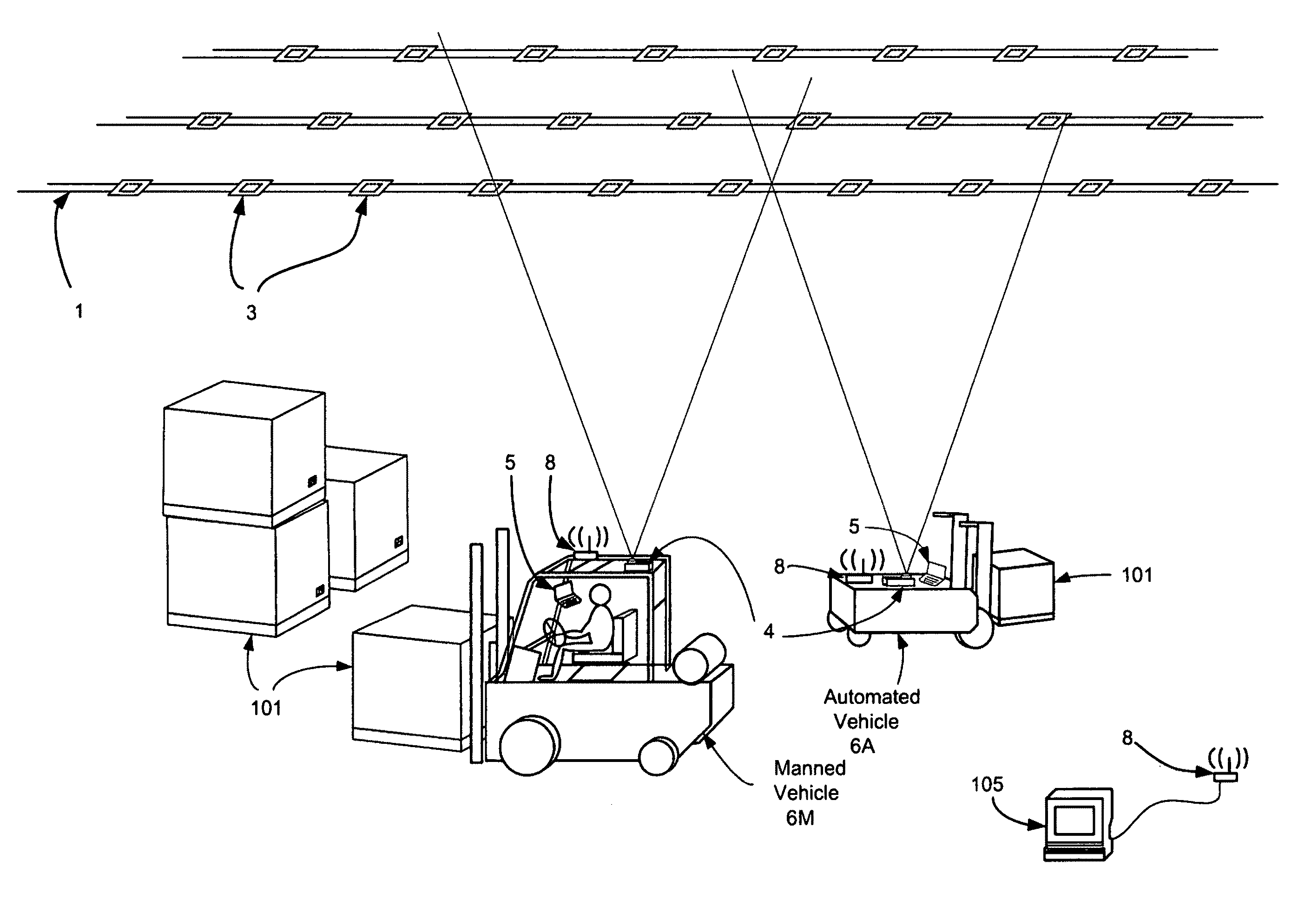
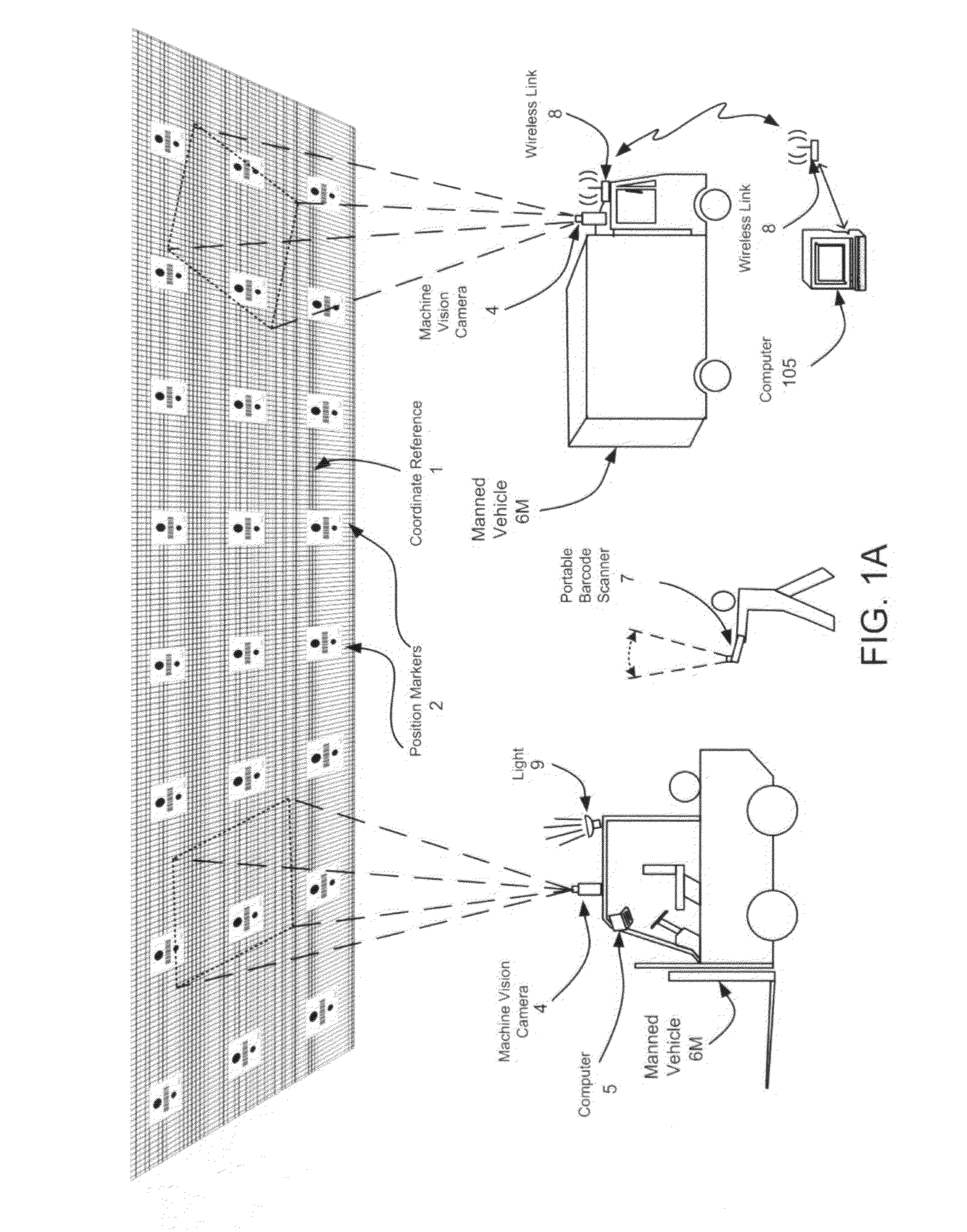
[0134]The apparatus of the first embodiment is illustrated in FIGS. 1A, and 3 through 6. A Position Marker Look-Up Table is shown in FIG. 7. FIG. 8 presents a high level software flow diagram for the general solution for position and rotational orientation determination. FIGS. 9 through 11 are software flow diagrams that show the method for image processing, feature processing, determination of expected position and rotational orientation and the calculation of actual position and rotational orientation.

[0135]In this example, the vehicles have freedom of motion in two dimensions within the operating area; therefore, the invention embraces two-dimensional analysis, plus single degree-of-freedom rotation (heading) determination.

[0136]Referring to FIG. 1A, a first embodiment of the invention will now be described in detail. The plurality of position markers 2 are preferably supported in rows on cords in accordance with the teachings of U.S. application Ser. No. 12 / 319,825. Alternativel...

second embodiment

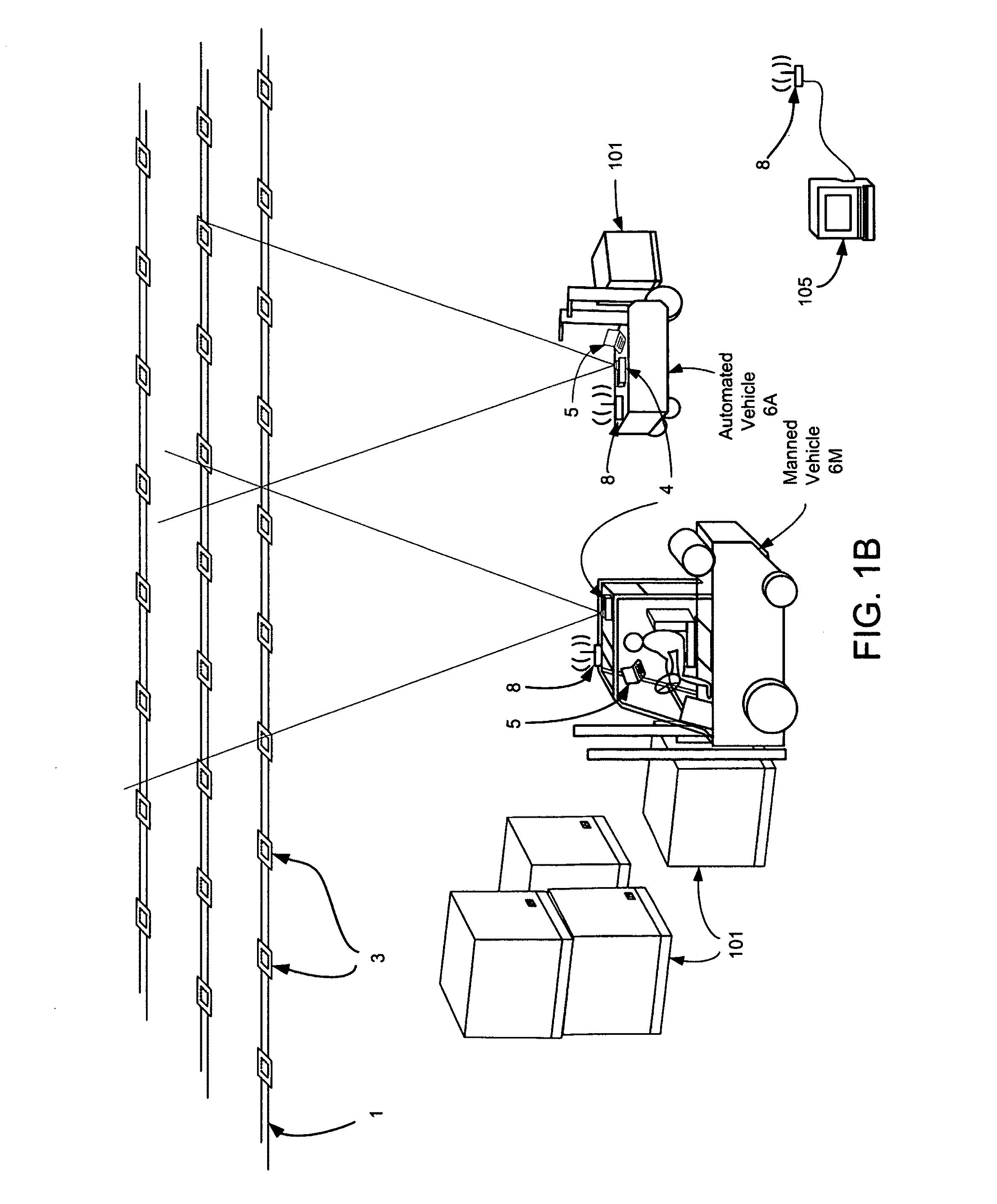
[0171]The apparatus of the second embodiment is illustrated in FIGS. 1B, 2, 8 and 12 through 15. A Position Marker Look-Up Table is shown in FIG. 16. FIG. 8 presents a high level software flow diagram for the general solution for position and rotational orientation determination. FIGS. 17 through 19 are software flow diagrams that show the method for image processing, feature processing, and determination of expected position and rotational orientation and the calculation of actual position and rotational orientation.

[0172]Referring to FIGS. 1B and 2, a second embodiment will now be described. This embodiment utilizes two-dimensional bar codes. Coordinate reference 1 consists of position markers 3 (FIG. 12), which are fabricated of labels 3b and substrates 3a. Bar code symbols, each containing a unique identification encoded in two-dimensional bar code symbology are printed on the label stock, along with human readable text. Bar codes of standard formats can be used including Datama...

example 1

[0223]FIG. 26 illustrates a first example of a warehouse operation. Two vehicles are shown; 106 which is automated and 107 which may be automated or manned. A plurality of obstructions B1 through B11 (which may be storage racks or building structure) and an obstruction 108 representing a roof support column and an office area B12 are shown. An array of position markers 103 is shown.

[0224]Preparatory to commencing warehouse operations a map of the coordinate space (i.e., the warehouse) is created to determine allowable travel routes for vehicles and locations of obstacles within the coordinate space, and the map is stored within a memory in a vehicle controller (that is implemented by computer 105).

[0225]In this example the system has determined that vehicle 106 is initially at position 106(t0) and that vehicle 107 is at position 107(t0). The vehicle controller 105 receives a request to move a load 101 from bulk storage area B8 to position 8 on Rack B11. The vehicle controller 105 de...


PUM


Abstract

A method and apparatus for managing manned and automated utility vehicles, and for picking up and delivering objects by automated vehicles. A machine vision image acquisition apparatus determines the position and the rotational orientation of vehicles in a predefined coordinate space by acquiring an image of one or more position markers and processing the acquired image to calculate the vehicle's position and rotational orientation based on processed image data. The position of the vehicle is determined in two dimensions. Rotational orientation (heading) is determined in the plane of motion. An improved method of position and rotational orientation is presented. Based upon the determined position and rotational orientation of the vehicles stored in a map of the coordinate space, a vehicle controller, implemented as part of a computer, controls the automated vehicles through motion and steering commands, and communicates with the manned vehicle operators by transmitting control messages to each operator.

Description

PRIORITY CLAIM[0001]This application claims the benefit of U.S. Provisional Application 61 / 397,927, filed 18 Jun. 2010.RELATED APPLICATIONS[0002]This application is a continuation-in-part of U.S. application Ser. No. 11 / 292,463, filed Dec. 3, 2005, entitled “METHOD AND APPARATUS FOR DETERMINING POSITION AND ROTATIONAL ORIENTATION OF AN OBJECT”.[0003]U.S. application Ser. No. 12 / 319,825 filed Jan. 13, 2009, entitled “OPTICAL POSITION MARKER APPARATUS”, U.S. application Ser. No. 12 / 459,728 filed Jul. 7, 2009, entitled “METHOD AND APPARATUS FOR COLLISION AVOIDANCE” and U.S. application Ser. No. 12 / 321,836, filed Jan. 26, 2009, entitled “APPARATUS AND METHOD FOR ASSET TRACKING” are also related to this application.SCOPE OF THE INVENTION[0004]The invention presents a method and apparatus for managing manned and automated utility vehicles in a coordinate space utilizing a method and apparatus that optically determines the position and the rotational orientation of vehicles in a three-dime...

Claims


Application Information

Patent Timeline
IPC IPC(8): G06F7/00G05D1/02G01C21/00
CPCG01S5/16G01S5/163G05D2201/0216G05D1/0274G05D1/0291G05D1/0234G01C21/206
Inventor KUNZIG, ROBERT S.TAYLOR, ROBERT M.EMANUEL, DAVID C.MAXWELL, LEONARD J.
Owner SHENZHEN INVENTION DISCOVERY CO LTD
Why Eureka
Try Eureka