Imaging device, imaging method and recording medium

Inactive Publication Date: 2011-01-20
FUJIFILM CORP
View PDF5 Cites 68 Cited by
  • Summary
  • Abstract
  • Description
  • Claims
  • Application Information

AI Technical Summary

Benefits of technology

[0025]According to the presently disclosed subject matter, a difference in evaluation of the imaging conditions (for example, the difference in the focused positio

Problems solved by technology

In this case, an appropriate stereoscopic image cannot be obtained.
However, a mechanism for changing t

Method used


Image

  • Imaging device, imaging method and recording medium
  • Imaging device, imaging method and recording medium
  • Imaging device, imaging method and recording medium

Examples


first embodiment

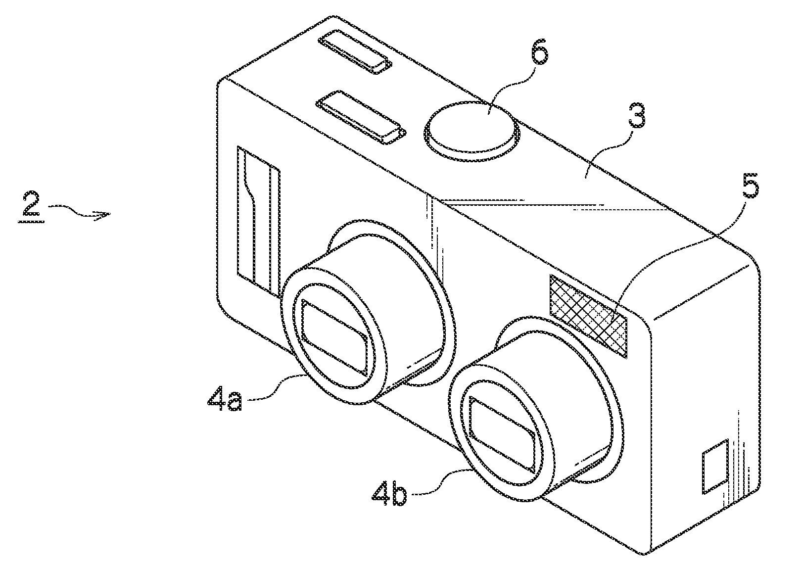
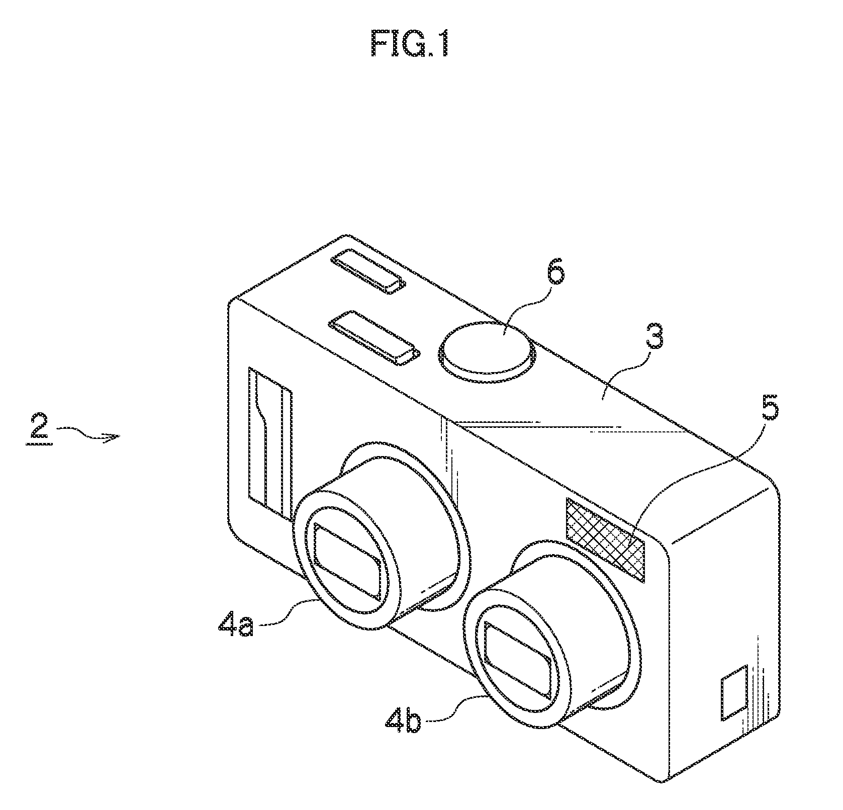
[0057]FIG. 1 illustrates a front side perspective view of a camera 2. In FIG. 1, on the front surface of the camera 2, a first lens barrel 4a which includes a first image taking optical system 1a, and a second lens barrel 4b which includes a second image taking optical system 1b are built in. In addition, a flash 5 and the like are exposed on the front surface of the camera 2. The first and second lens barrels 4a and 4b are provided side by side at a regular interval in a horizontal direction, and extend forward from a camera main body 3 at the time of an image taking mode, and are contained in the camera main body 3 when power is turned off or at the time of an image reproduction mode. Moreover, on the upper surface of the camera 2, a shutter button 6 used for a shutter release operation is provided.

[0058]On the back surface of the camera 2 (not illustrated), an operation unit 10 including a zoom button, a menu button, and a cursor button, and a monitor 11 are provided. According t...

second embodiment

[0111]It is assumed that, if there is no subject at the intersection point (also referred to as “cross point”) between the optical axes L1 and L2 of the first image taking optical system 1a and the second image taking optical system 1b (see FIG. 6), an AE process of the spot exposure metering system is executed. If it is assumed that a spot metering area is set at the same position (for example, the image central portion) in both the first image taking optical system 1a and the second image taking optical system 1b as the conventional art, the subjects included in the spot metering areas in the first and second image data are different due to the effects of the parallax, and thus, exposures of the first image taking optical system 1a and the second image taking optical system 1b, which are set by the AE process, are also different. If an exposure level is greatly different between the left and right images, the appropriate stereoscopic image cannot be obtained, which makes the viewe...

third embodiment

[0123]It is assumed that, if there is no subject at the intersection point (also referred to as “cross point”) between the optical axes L1 and L2 of the first image taking optical system 1a and the second image taking optical system 1b (see FIG. 6), the AE process of the weighted average metering is executed. If it is assumed that a weight for appropriate exposure value calculation corresponding to each small region partitioning the image is set as the same in both the first image taking optical system 1a and the second image taking optical system 1b as the conventional art, a subject portion included in the small region at the same position is different between the first and second image data due to the effects of the parallax, and thus, the exposures of the first image taking optical system 1a and the second image taking optical system 1b, which are set by the AE process, are also different. If the exposure level is greatly different between the left and right images, the appropri...


PUM


Abstract

An imaging method includes: calculating an amount of parallax between a reference optical system and an adjustment target optical system; setting coordinates of an imaging condition evaluation region corresponding to the first viewpoint image outputted by the reference optical system; calculating coordinates of an imaging condition evaluation region corresponding to the second viewpoint image outputted by the adjustment target optical system, based on the set coordinates of the imaging condition evaluation region corresponding to the first viewpoint image, and on the calculated amount of parallax; and adjusting imaging conditions of the reference optical system and the adjustment target optical system, based on image data in the imaging condition evaluation region corresponding to the first viewpoint image, at the set coordinates, and on image data in the imaging condition evaluation region corresponding to the second viewpoint image, at the calculated coordinates, and outputting the viewpoint images in the adjusted imaging conditions.

Description

BACKGROUND OF THE INVENTION[0001]1. Field of the Invention[0002]The presently disclosed subject matter relates to an imaging device including a plurality of optical systems having a parallax, and more particularly, to a technique of preventing or minimizing a difference in an AF (automatic focus adjustment process) process or an AE (automatic exposure process) process between the plurality of optical systems.[0003]2. Description of the Related Art[0004]Japanese Patent Application Laid-Open No. 2005-173270 discloses a stereoscopic image taking optical device which causes left and right parallax images formed through left and right objective optical systems, to be alternately imaged, and also can adjust a convergence distance between the left and right objective optical systems by rotating mirrors provided in the left and right objective optical systems respectively. The stereoscopic image taking optical device includes an auto-focus device having an auto-focus function, and an auto-f...

Claims


Application Information

Patent Timeline
IPC IPC(8): H04N13/02H04N5/228G02B7/28G02B7/36G03B7/28G03B13/36G03B19/07G03B35/10H04N13/239
CPCH04N5/23212H04N5/2351H04N5/2354H04N13/0296H04N13/0239H04N13/0246H04N13/0253H04N13/0055H04N13/254H04N13/189H04N13/246H04N13/296H04N13/239H04N23/673H04N23/71H04N23/74
Inventor PAN, YI
Owner FUJIFILM CORP
Why Eureka
Try Eureka