Digital protective relay device and data transmission device for the same

a technology of digital protective relay and data transmission device, which is applied in the direction of repeater/relay circuit, transmission monitoring, baseband system details, etc., can solve the problem that a high-performance protective relay device capable of complex processing cannot be constructed, and achieve high-precision and high-functional effects

Inactive Publication Date: 2011-01-20
KK TOSHIBA
View PDF3 Cites 9 Cited by
  • Summary
  • Abstract
  • Description
  • Claims
  • Application Information

AI Technical Summary

Benefits of technology

[0015]By means of this invention, an electrical quantity signal acquired from an electric power system is sampled at m times the fundamental frequency f0 (m>12) thereof, the sampled data is converted into m sampling data which are n-bit digital data (n>12), and the m sampling data of n bits with frequency m·f0 thus obtained are converted into k

Problems solved by technology

As explained above, in conventional technology, even when sampling is performed with high precision and digitally converted data is acquired by a protective relay device, due to constraints on the commun

Method used


Image

  • Digital protective relay device and data transmission device for the same
  • Digital protective relay device and data transmission device for the same
  • Digital protective relay device and data transmission device for the same

Examples


first embodiment

[0050]A first embodiment of the invention is explained, referring to FIG. 1 and FIG. 2.

CONFIGURATION

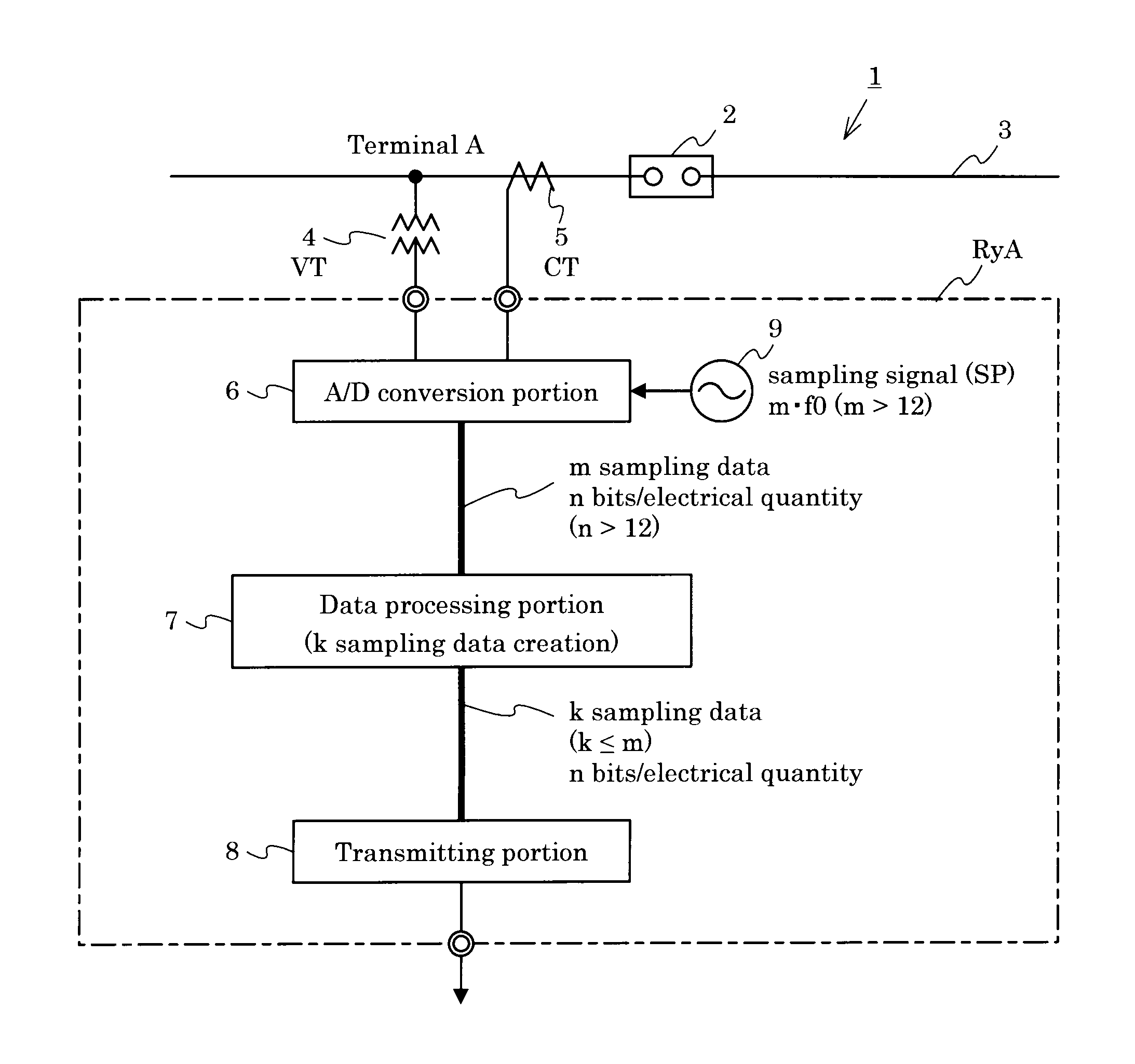
[0051]FIG. 1 is a system configuration diagram of the data transmission device for a digital protective relay device of this embodiment. The electric power system 1 connects a terminal A and an opposing terminal B, not shown, via a circuit breaker 2 and power transmission line 3. At each of the terminals (in FIG. 1, terminal A), a system voltage and system current (hereafter collectively called “system electrical quantities”), acquired by a voltage transformer (hereafter abbreviated “VT”) 4 and current transformer (hereafter abbreviated “CT”) 5, are input to a data transmission device TE, and are first converted into prescribed digital data by an analog / digital conversion portion (hereafter “A / D conversion portion”) 6. The converted digital data is subjected to necessary processing by a data processing portion 7, and is transmitted via a transmitting portion 8 to another digital prote...

second embodiment

[0065]A second embodiment of the invention is explained referring to FIG. 3 and FIG. 4.

CONFIGURATION

[0066]This embodiment relates to a current differential type digital protective relay device for power transmission line protection, to which the digital signal transmission device of the first embodiment is applied. This embodiment is explained taking a power transmission line protective relay device as an example; in addition, is also applicable to busbar protective relay devices, and is also applicable to a system stabilization device which collects instantaneous current value data from electric-supply stations distributed over a broad area, monitors system frequencies, and controls generators to stabilize the electric power system.

[0067]Below, the configuration of a digital protective relay device for power transmission line protection is explained, referring to FIG. 3.

[0068]The electric power system 1 connects a terminal A and an opposing terminal B, not shown, via a circuit brea...

third embodiment

[0093]A third embodiment of the invention is explained referring to FIG. 8.

CONFIGURATION

[0094]This embodiment is characterized in that the data processing portion 7 of the digital protective relay device RyA explained in the second embodiment is realized by an averaging portion 7-1 which performs processing to average data; otherwise the configuration is unchanged from that of the digital protective relay device RyA of the second embodiment, and so is omitted from the drawings.

[0095]The data processing portion 7A of this embodiment employs the averaging portion 7-1 to realize a method of converting the sampling data of FIG. 4(a) described above into the sampling data of FIG. 4(b). The averaging portion 7-1 performs averaging the input m sampling data of n bits / electrical quantity with sampling frequency of m·f0, and by this means performs conversion into and outputs k sampling data of n bits / electrical quantity with frequency k·f0 (k≦m).

[0096]In this embodiment, electrical quantitie...


PUM


Abstract

Provided is a high-precision and highly functional digital protective relay device and a data transmission device for a digital protective relay device, by enabling transmission of large amounts of system electrical quantity data. The data transmission device for a digital protective relay device, the transmission device comprising: an analog/digital conversion portion 6, which, after sampling a system electrical quantity signal acquired from an electric power system at m times the fundamental frequency f0 (m>12) thereof, performs conversion into n-bit digital data (n>12); a data processing portion 7, which converts m sampling data of n bits with frequency m·f0, obtained by the analog/digital conversion portion, into k sampling data with frequency k·f0 (k≦m) at or below the former frequency; and a transmitting portion 8, which transmits k sampling data obtained by the data processing portion to another protective relay device in a prescribed transmission format.

Description

TECHNICAL FIELD[0001]This invention relates to a digital protective relay device which protects a power transmission line or other electric power system, and to a data transmission device for a digital protective relay device which transmits signals used in digital protection computation.BACKGROUND ART[0002]A protective relay device is installed for the purpose of maintaining stable operation of an electric power system, when a fault which has occurred in a busbar, transformer, power transmission line, or other electric power system equipment is detected, by detaching the fault equipment from the robust electric power system.[0003]In a important electric power system equipment, often a current differential protective relay device with excellent protection performance is applied as a protective relay device.[0004]A current differential protective relay device takes as inputs the currents flowing at both ends of an equipment to be protected and performs a differential operation to det...

Claims


Application Information

Patent Timeline
IPC IPC(8): H04L25/20
CPCH02H3/30H02H1/0061
Inventor FUKUSHIMA, KAZUTOSUGIURA, HIDEAKISAGA, MASAMICHI
Owner KK TOSHIBA
Why Eureka
Try Eureka