Milling tool for machining work pieces

a technology for machining work pieces and milling tools, which is applied in the direction of milling cutters, milling equipment, and profiled circular tools, etc., can solve the problems of rotatably mounted indexable cutting inserts, high construction costs, and limited us

Active Publication Date: 2011-01-20
POKOLM FRANZ JOSEF
View PDF24 Cites 7 Cited by
  • Summary
  • Abstract
  • Description
  • Claims
  • Application Information

AI Technical Summary

Benefits of technology

[0006]The invention therefore has the object of developing a milling head for machining work pieces comprising radially disposed, rotatably mounted indexable cutting inserts in such a way that the embedment for mounting the blades becomes substantially simpler and, in particular, the process of exchanging the cutting inserts becomes substantially simpler.SOLUTION

Problems solved by technology

With the said solutions for milling tools known from the prior art which are equipped with rotatably mounted cutting disks, it is considered as disadvantageous that the embodiments known to the art are very costly to build with regard to their rotatably mounted indexable cutting inserts, which is due to the costly design of the mounting for the indexable cutting insert.
An additional disadvantage of the solutions known to the art is seen in the fact that in particular with regard to the storage inventory of rotatably mounted indexable cutting inserts, indexable cutting inserts particularly adapted to the milling head have to be kept available in storage.

Method used


Image

  • Milling tool for machining work pieces
  • Milling tool for machining work pieces
  • Milling tool for machining work pieces

Examples


Embodiment Construction

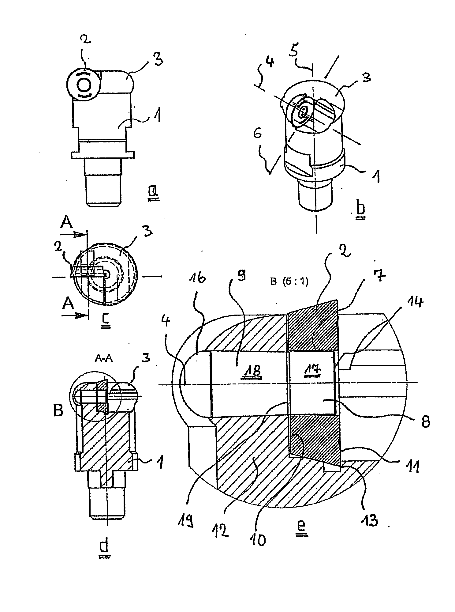
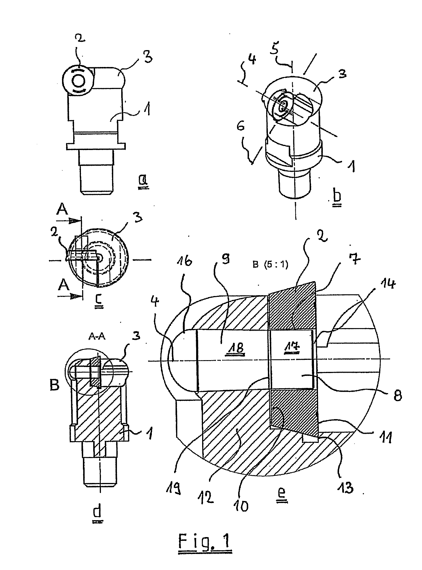
[0036]FIG. 1 shows an initial embodiment of a milling tool 1 according to the invention, wherein the milling tool 1 can be seen once in each detail view, in the lateral view a, in the perspective view b, in the top view c, as well as in the sectional exposed view d. The detail view e, in particular, shows the arrangement of an indexable cutting insert 2 on the milling head 3 in sectional exposed representation. The milling tool 1 here is intended to machine work pieces, and at least one radially disposed indexable cutting insert 2 is provided on the milling head 3 of the milling tool 1, said indexable cutting insert 2 being rotatably mounted on a rotational-symmetrically designed Y axis 4 on the milling head 2. As can be seen, in particular, from the perspective representation of FIG. 1b, the Z axis in particular forms the rotational axis 5 of the milling tool 1, while the X axis occupies the cutting horizon designated by the reference number 6.

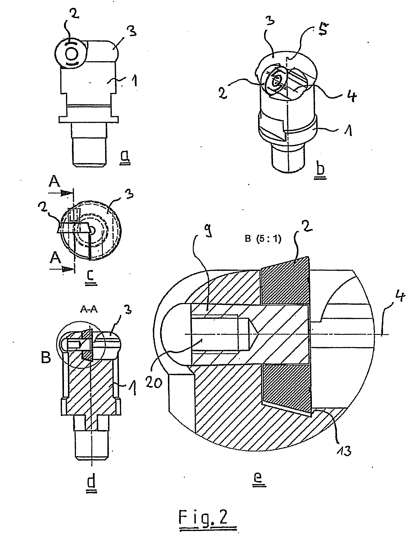
[0037]It is now easily understood that...


PUM

PropertyMeasurementUnit
areaaaaaaaaaaa
shapeaaaaaaaaaa
adhesion forcesaaaaaaaaaa

Abstract

The invention related to a milling tool (1) for machining work pieces, comprising at least one blade that is arranged in a radial manner on the milling head (2) that is rotationally mounted on a rotationally symmetrical designed Y-axis (4) on the milling head. According to the invention, said indexable cutting insert (2) is arranged below a tolerance play (7) in a freely rotating manner on the free end (8) of a mounting pin (9) secured in a detachable manner to the milling head (3) below the clamping seat. The freely rotationally mounted indexable cutting insert (2) is mounted or surrounded on the entire surface of the rear side (10) and on certain pats on the front side (11) such that the mounting pin (9) does not detach itself from the material (12) of the milling head (3).

Description

BACKGROUND OF THE INVENTION[0001]The invention relates to a milling tool for machining work pieces comprising at least one blade disposed on the milling head, said blade being in the form of an indexable cutting insert rotatably mounted on a radially rotation-symmetrically designed Y axis on the milling head.PRIOR ART[0002]Machining with rotating blades has been a well known procedure for years though the procedure has obtained distinctiveness in manufacture to only a small degree. In the present case, a tool is used the active element whereof comprises a round, rotatably mounted disk blade, said disk blade executing during the machining process an automatic rotational movement kinematicly-based on the machining process and on the fact that the disk blade axis is slanted in relation to the cutting direction. Due to the said rotating movement of the disk blade during machining, a new part of the blade is always engaged in continuous sequence, whereby each point on the blade remains o...

Claims


Application Information

Patent Timeline
Patent Type & Authority Applications(United States)
IPC IPC(8): B23C5/22B23C5/02
CPCB23C2210/506B23C2210/165B23C2210/168Y10T407/12B23C2200/045Y10T407/24Y10T407/2274Y10T407/20B23C5/2221Y10T407/1936B23C5/2213
Inventor POKOLM, FRANZ JOSEF
Owner POKOLM FRANZ JOSEF
Why Eureka
Try Eureka