Machining Method and Machine Tool

a technology of machine tools and machining methods, applied in the field of machine tools, can solve problems such as the inability to completely prevent and achieve the effect of preventing the breakage of the machine tool

Active Publication Date: 2011-01-20
MAKINO MILLING MASCH CO LTD
View PDF11 Cites 14 Cited by
  • Summary
  • Abstract
  • Description
  • Claims
  • Application Information

AI Technical Summary

Benefits of technology

[0004]However, in the above prior art, since the reverse command is given to the servomotor after collision has been detected, the driven body ...

Problems solved by technology

Therefore, it is impossible to compl...

Method used


Image

  • Machining Method and Machine Tool
  • Machining Method and Machine Tool
  • Machining Method and Machine Tool

Examples


Embodiment Construction

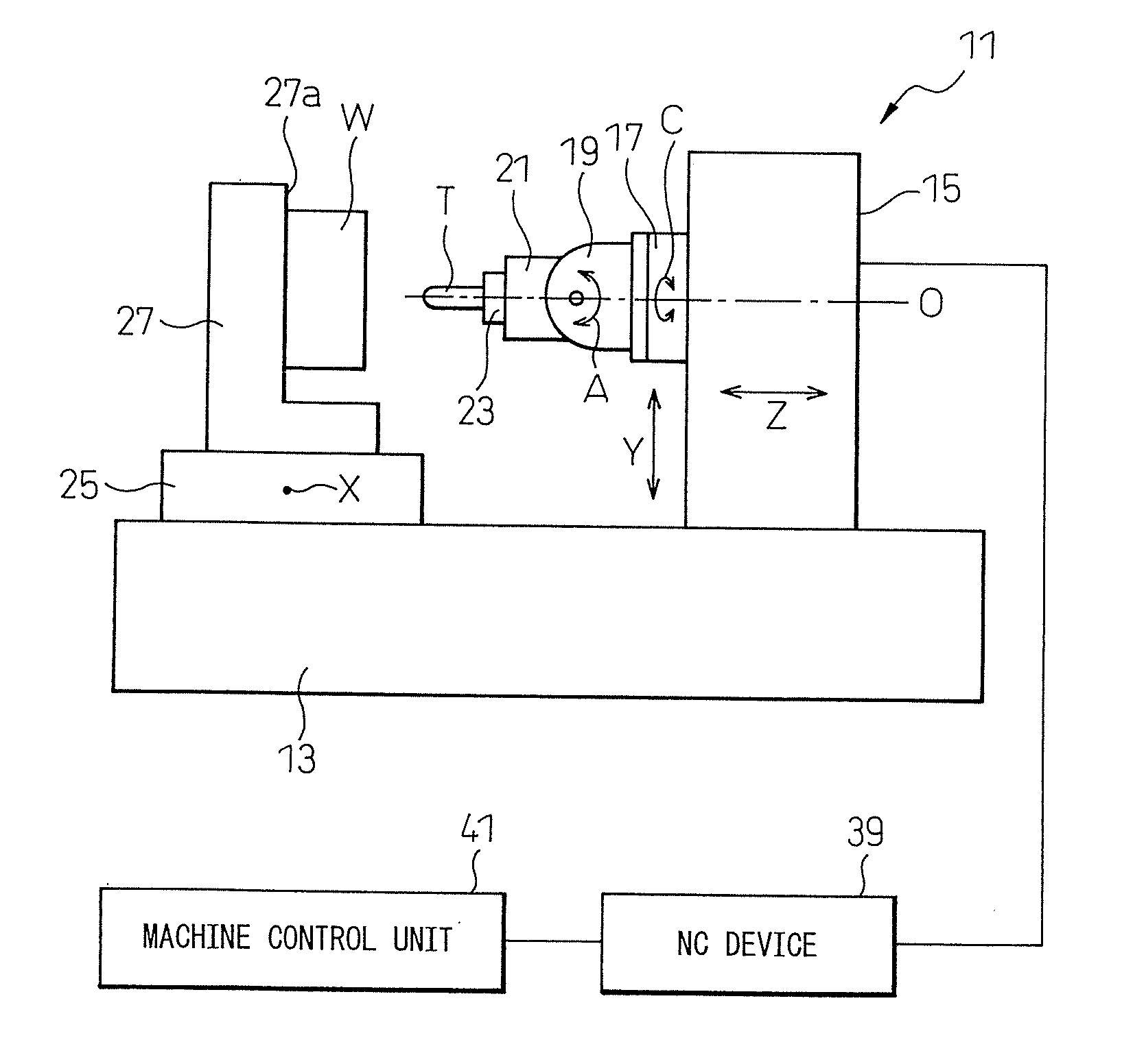
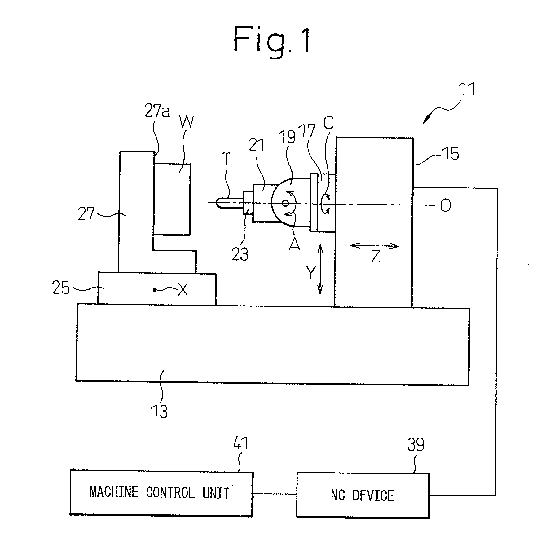
[0013]Referring to FIG. 1, a machine tool 11 according to a preferred embodiment of the present invention is a five-axis NC milling machine which comprises a bed 13 fixed onto a floor of a factory. A column 15 is mounted to the upper face of the bed 13 for linear motion relative to the bed 13 in a horizontal longitudinal direction (the direction of Z-axis, i.e., the right-and-left direction in FIG. 1). A head stock 17 is mounted to the front face of the column 15 for linear motion relative to the column 15 in the vertical direction (the direction of Y-axis, i.e., the up-and-down direction in FIG. 1).

[0014]Although not shown in detail in the drawing, the machine tool 11 includes X-, Y- and Z-axis feed motors for moving a workpiece W relative to a tool T in the directions of X-, Y- and Z-axes, an NC device 39 for controlling the X-, Y- and Z-axis feed motors, and a machine control unit 41 which reads a machining program and sends motion commands to the NC device 39 and tool change com...


PUM

PropertyMeasurementUnit
Torqueaaaaaaaaaa

Abstract

A minimum five-axis machine tool (11) has first to third linear feed axes orthogonal to each other as well as first and second rotational feed axes orthogonal to each other, wherein a rotational axis line of the first rotational feed axis C is parallel to the first linear feed axis Z. While a tool T and a work W are moved relatively through the second and third linear feed axes X, Y to perform machining of the work W by means of the tool T, the machine tool controls the first rotational feed axis C such that a rotational axis line of the second rotational feed axis A is perpendicular to the direction of relative movement of the perpendicular to the direction of relative movement of the tool T to the work W, and controls a power supplied to a motor for the second rotational feed axis A when a torque around the second rotational feed axis A exceeds a specified threshold.

Description

TECHNICAL FIELD[0001]The present invention relates to a machine tool. More particularly, the present invention relates to a machining method and a machine tool, improved to prevent a machine tool from being damaged by an overload due to a collision of a tool with a workpiece or by a breakage of a tool.BACKGROUND ART[0002]An excessively large force may be applied to a main spindle of a machine tool such as an NC milling machine, when a tool is broken during a process for machining a workpiece or when a tool collides with the workpiece.[0003]In order to prevent the above problems, for example, JP-A-3-3687 discloses a method of preventing collision of a body driven by a servomotor. According to the method, when collision is detected, the servomotor receives a predetermined speed command, the direction of which is reverse to that of the actual speed of the servomotor, for a predetermined period of time so as to reverse the servomotor.DISCLOSURE OF THE INVENTION[0004]However, in the abov...

Claims


Application Information

Patent Timeline
IPC IPC(8): B23Q5/58B23Q11/00
CPCB23Q11/04B23Q15/007G05B19/4062G05B2219/37342G05B2219/37632G05B2219/42288G05B2219/49155G05B2219/50155G05B2219/50205Y10T409/303752Y10T409/303808Y10T409/30392Y10T409/306832Y10T409/307224Y10T409/307672Y10T409/308512
Inventor TAKAHASHI, IKUMA
Owner MAKINO MILLING MASCH CO LTD
Why Eureka
Try Eureka