
Sample dispensing apparatus and automatic analyzer including the same

a technology of automatic analyzer and sample dispensing apparatus, which is applied in the direction of transportation and packaging, laboratory glassware, instruments, etc., can solve the problem of not being able to perform the dispensing operation independently, and achieve the effect of increasing the dispensing speed

Active Publication Date: 2011-01-20
HITACHI HIGH-TECH CORP
View PDF11 Cites 5 Cited by
  • Summary
  • Abstract
  • Description
  • Claims
  • Application Information

AI Technical Summary

Benefits of technology

The present invention provides a sample dispensing apparatus and an automatic analyzer including the sample dispensing apparatus, which has a plurality of dispensing probes capable of performing the dispensing operations independently of each other, and can increase a dispensing speed while realizing the dispensing operations at flexible timings. The sample dispensing apparatus includes a sample container loading mechanism, a reaction cuvette loading mechanism, and a sample dispensing mechanism. The sample container loading mechanism can move the position of each sample container, while the reaction cuvette loading mechanism can move the reaction cuvettes between the sample container and the reaction cuvette independently of each other. The sample dispensing mechanism includes nozzles for sucking and discharging the sample, which can perform the dispensing operations independently of each other. The sample container loading mechanism may be a sample disk or a rack capable of loading one or more sample containers. The reaction cuvette loading mechanism may be a reaction disk or a structure capable of linearly moving the reaction cuvettes. The technical effects of the invention are increased dispensing speed and flexibility in performing the dispensing operations.

Problems solved by technology

According to the embodiment described in Patent Reference 1, however, the two dispensing probes are supported by one probe shaft and they cannot perform the dispensing operations independently of each other.

Method used


Image

  • Sample dispensing apparatus and automatic analyzer including the same
  • Sample dispensing apparatus and automatic analyzer including the same
  • Sample dispensing apparatus and automatic analyzer including the same

Examples


Embodiment Construction

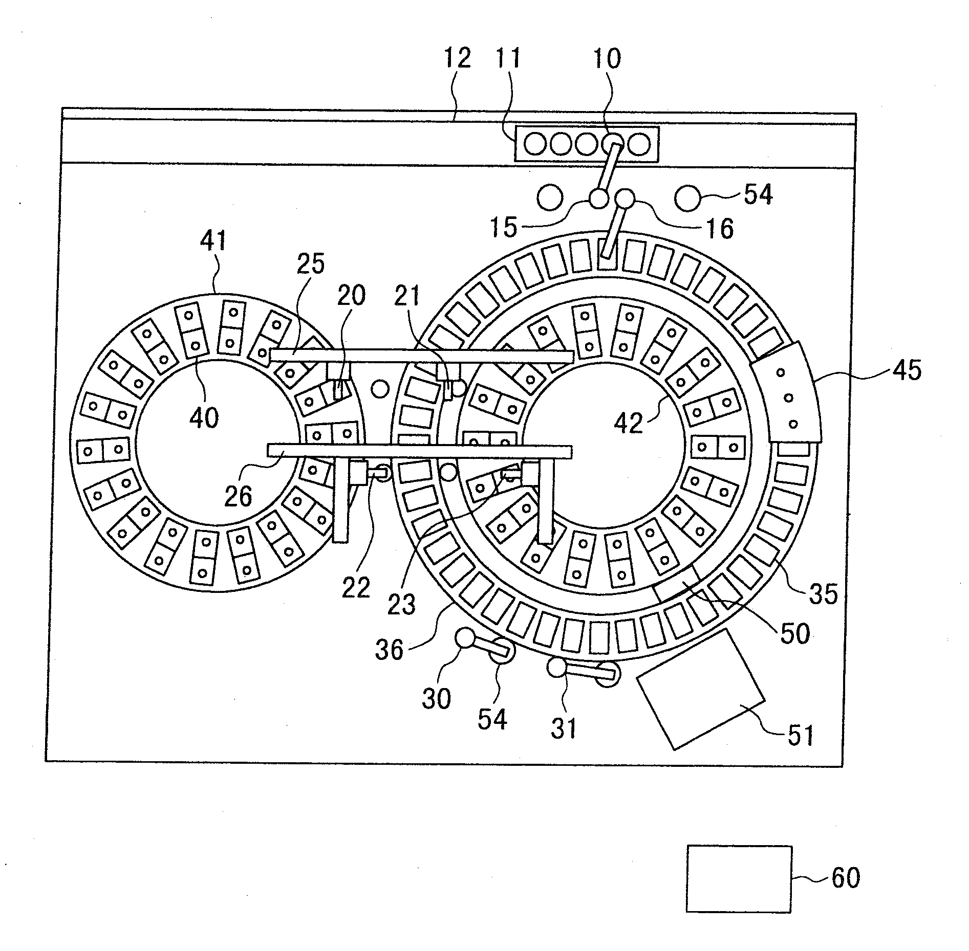
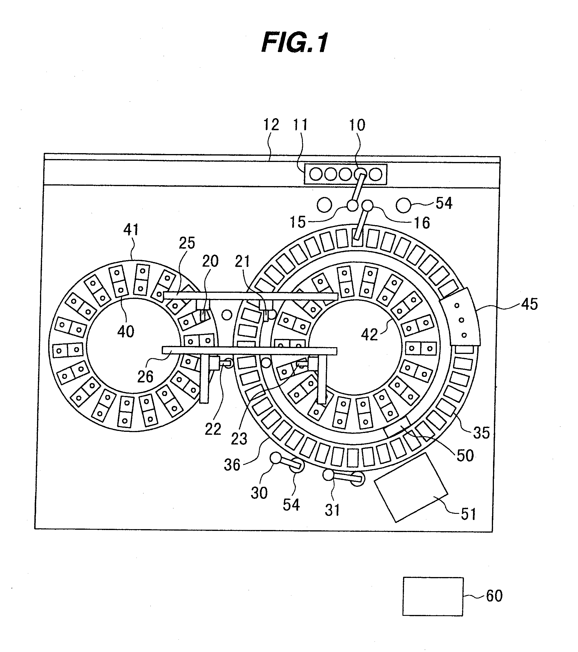
[0026]In the present invention, each of the sample dispensing mechanisms repeats operations of sucking the sample and discharging the sucked sample into the reaction cuvette. The provision of the plurality of nozzles enables those operations to be performed such that while one sample dispensing mechanism discharges the sample into the reaction cuvette on the reaction disk after sucking the sample, the other nozzle sucks the sample. Accordingly, the standby time of the nozzle until it starts the suction of the sample can be cut down and high-speed processing can be realized.

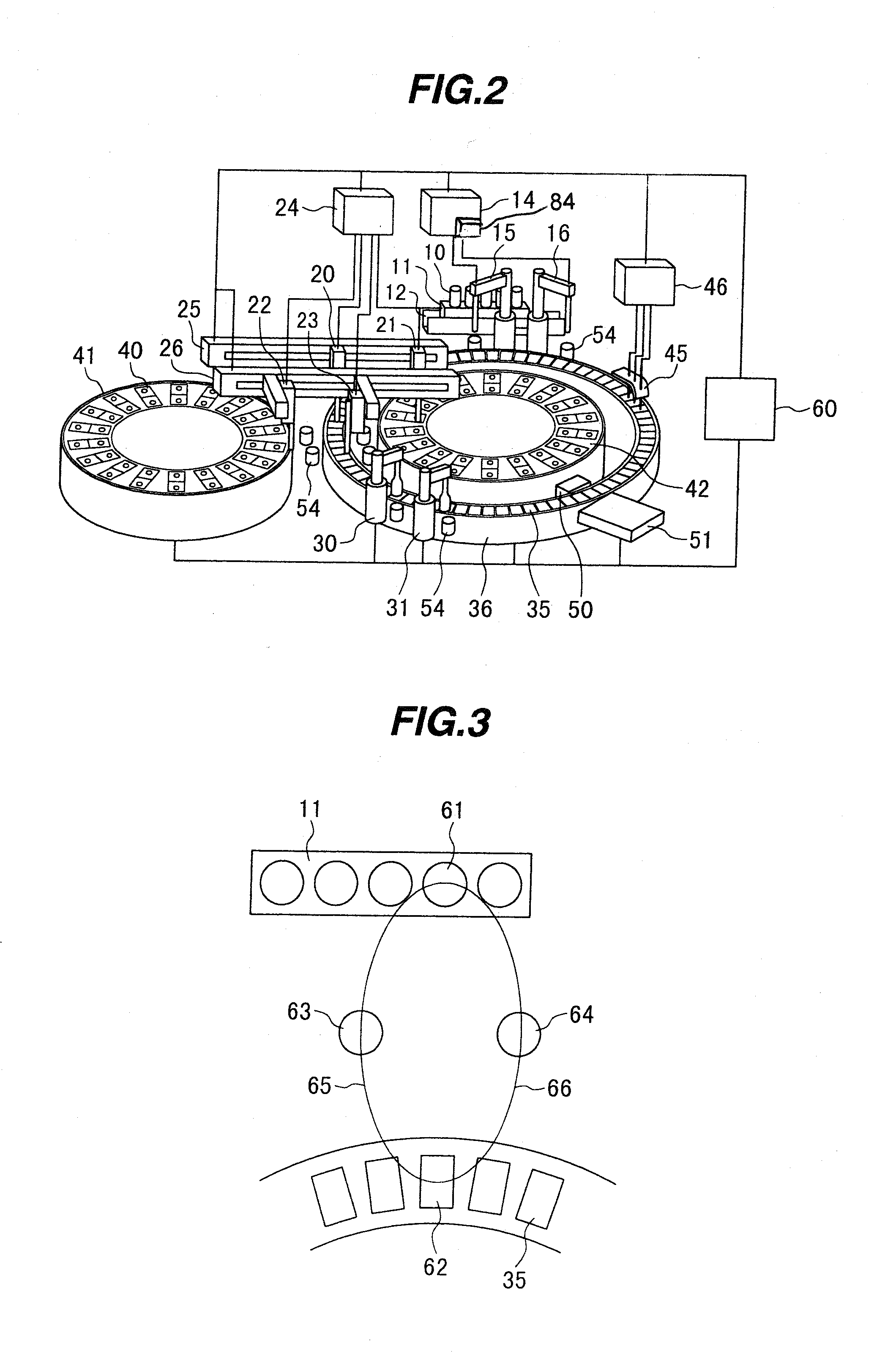
[0027]Because a plurality of sample dispensing mechanisms are able to carry out the dispensing operations independently of each other, the sample can be sucked from the sample container at a shorter interval. Correspondingly, the time allowed for the sample container to move to a sample suction position is shortened and a difficulty rises in moving the sample container to one predetermined location in time. This a...


PUM


Abstract

The invention provides a small-sized automatic analyzer being compact, enabling a large number of analysis items to be carried out, and having a high processing speed. The automatic analyzer is particularly suitably applied to a medical analyzer used for qualitative / quantitative analysis of living body samples, such as urine and blood. A plurality of sample dispensing mechanism s capable of being operated independently of each other are provided to suck a sample from any one of a plurality of sample suction positions and to discharge the sucked sample to any one of a plurality of positions on a reaction disk. The automatic analyzer having a high processing capability can be thus realized without increasing the system size.

Description

[0001]This is a continuation application of U.S. application Ser. No. 10 / 780,743, filed Feb. 19, 2004, now allowed, which claims priority to JP 2003-74751, filed Mar. 19, 2003, the contents of which are hereby incorporated by reference into this application.BACKGROUND OF THE INVENTION[0002]1. Field of the Invention[0003]The present invention relates to a sample dispensing apparatus for use in an analyzer in which a sample and a reagent are mixed with each other to carry out qualitative / quantitative analysis of a particular ingredient in the sample, and to an automatic analyzer including the sample dispensing apparatus. More particularly, the present invention relates to a sample dispensing apparatus with a high sampling (pipetting) capability per hour, and to an automatic analyzer including the sample dispensing apparatus.[0004]2. Description of the Related Art[0005]Taking as an example a medical automatic analyzer used for analyzing particular ingredients in living body samples, su...

Claims


Application Information

Patent Timeline
Patent Type & Authority Applications(United States)
IPC IPC(8): G01N21/00G01N35/00G01N35/02G01N35/10
CPCG01N35/0092G01N35/025G01N35/1009G01N35/1065G01N35/109G01N2035/1018Y10T436/2575G01N2035/1076G01N2035/1086Y10T436/11Y10T436/111666Y10T436/114998G01N2035/1025B01F31/44G01N35/021G01N35/1002G01N35/1004G01N35/1011G01N35/1016G01N35/1095G01N2035/00237G01N2035/0406
Inventor YANAMI, HIDEYUKIYAMAZAKI, ISAOHANAWA, MASAAKIOTAKE, HITOSHI
Owner HITACHI HIGH-TECH CORP
Learn More