
Audio signal classifier

Active Publication Date: 2011-01-20
NOKIA TECHNOLOGLES OY
View PDF1 Cites 41 Cited by
  • Summary
  • Abstract
  • Description
  • Claims
  • Application Information

AI Technical Summary

Benefits of technology

[0017]In embodiments of the invention it is possible to more efficiently classify the type of audio signal to be encoded, and as such it is possible to more efficiently and / or more accurately encode the audio signal based on this classification of the audio signal.

Problems solved by technology

Whilst incorporation of a typical audio signal classifier into the audio coder is possible, it is not always feasible to execute such an algorithm especially within the limited processing capacity of an electronic device such as a hand held computer or mobile communication device.

Method used


Image

  • Audio signal classifier
  • Audio signal classifier
  • Audio signal classifier

Examples


first embodiment

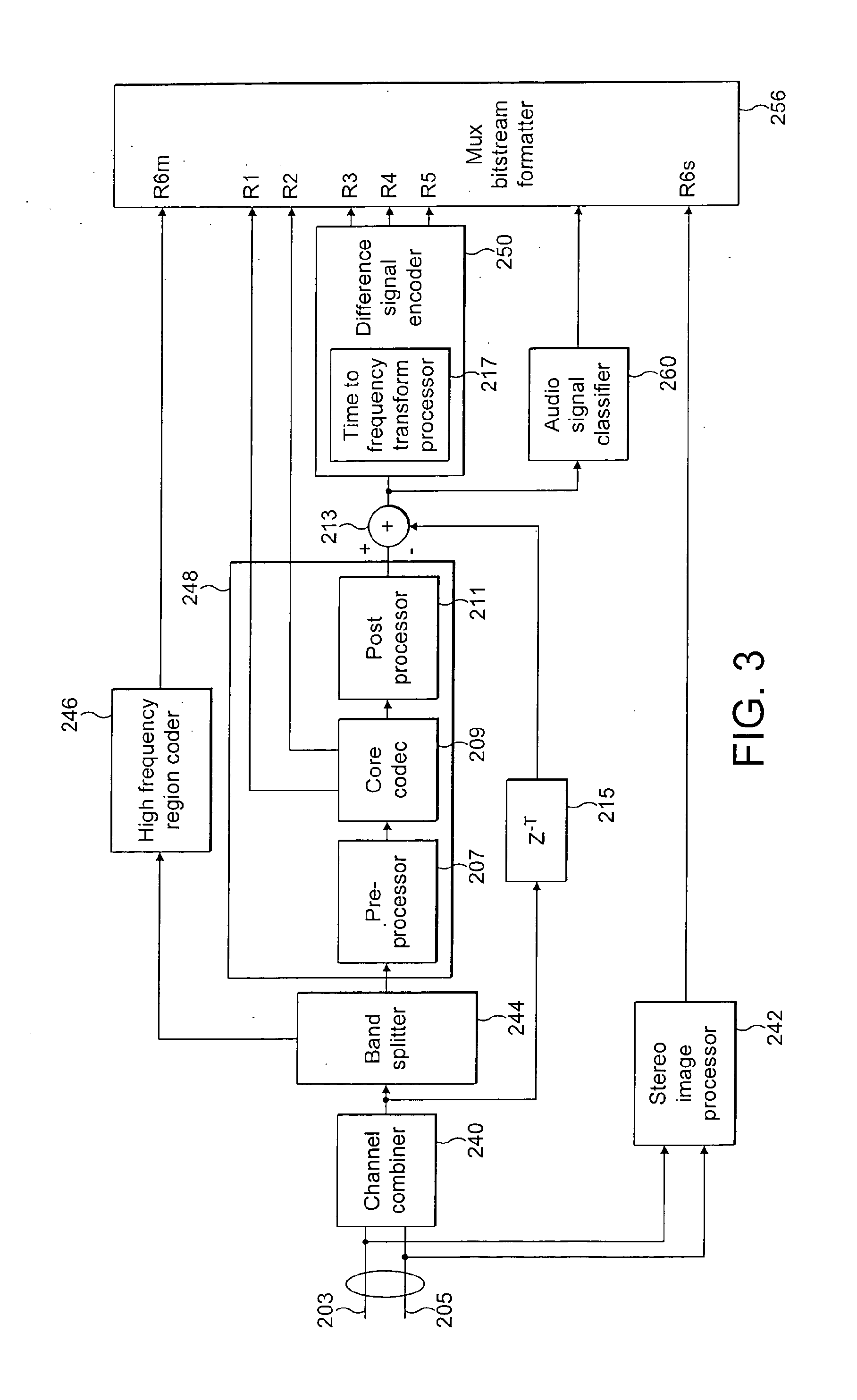
[0091]FIG. 3 shows schematically an encoder 104 according to the invention. The encoder 104 is depicted as comprising a pair of inputs 203 and 205 which are arranged to receive an audio signal of two channels. It is to be understood that further embodiments of the present invention may be arranged such that the encoder 104 comprises a single channel mono input. Further still, embodiments of the invention may be arranged to receive more than two channels such as the collection of channels associated with a 5.1 surround sound audio configuration.

[0092]In a first embodiment of the invention the input channels 203 and 205 are connected to a channel combiner 240, which combines the inputs into a single channel signal. However, further embodiments of the present invention which may be configured to receive a single channel input may not have a channel combiner.

[0093]The channel inputs 203 and 205 may also be each additionally connected to a stereo image processor 242. The stereo image pro...

second embodiment

[0095]In the present invention this higher frequency band signal may be encoded with a higher frequency region coder that may solely act on the higher frequency band signal to be encoded and does not utilise information from the lower band to assist in the coding process. In further embodiments of the invention, there may be no requirement or need to perform band width expansion on the input audio signal. In these embodiments of the invention the codec may be arranged to operate without the functional elements 246 and 244.

[0096]The core encoder 248, receives the audio signal to be encoded and outputs the encoded parameters which represent the core level encoded signal, and also the synthesised audio signal (in other words the audio signal is encoded into parameters and then the parameters are decoded using the reciprocal process to produce the synthesised audio signal). In embodiments of the invention as depicted in FIG. 3 the core encoder 248 may be divided into three parts (the pr...


PUM


Abstract

An apparatus for classifying an audio signal configured to: estimate at least one shaping parameter value for a plurality of samples of the audio signal; generate at least one audio signal classification value by mapping the at least one shaping parameter value to one of at least two interval estimates; and determine at least one audio signal classification decision based on the at least one audio signal classification value.

Description

FIELD OF THE INVENTION[0001]The present invention relates to audio signal classification and coding, and in particular, but not exclusively to speech or audio coding.BACKGROUND OF THE INVENTION[0002]Audio signals, like speech or music, are encoded for example by enabling an efficient transmission or storage of the audio signals.[0003]Audio encoders and decoders are used to represent audio based signals, such as music and background noise. These types of coders typically do not utilise a speech model for the coding process, rather they use processes for representing all types of audio signals, including speech.[0004]Speech encoders and decoders (codecs) are usually optimised for speech signals, and often operate at a fixed bit rate.[0005]An audio codec can also be configured to operate with varying bit rates. At lower bit rates, such an audio codec may work with speech signals at a coding rate equivalent to pure speech codec. At higher bit rates, the audio codec may code any signal i...

Claims


Application Information

Patent Timeline
IPC IPC(8): G06N5/02G10L19/22G10L25/78
CPCG10L25/78G10L19/22
Inventor VASILACHE, ADRIANALAAKSONEN, LASSE JUHANITAMMI, MIKKO TAPIORAMO, ANSSI SAKARI
Owner NOKIA TECHNOLOGLES OY
Learn More