
Scour preventive apparatus for pier foundation

Inactive Publication Date: 2011-01-27
JO DEOK RAE
View PDF9 Cites 3 Cited by
  • Summary
  • Abstract
  • Description
  • Claims
  • Application Information

AI Technical Summary

Benefits of technology

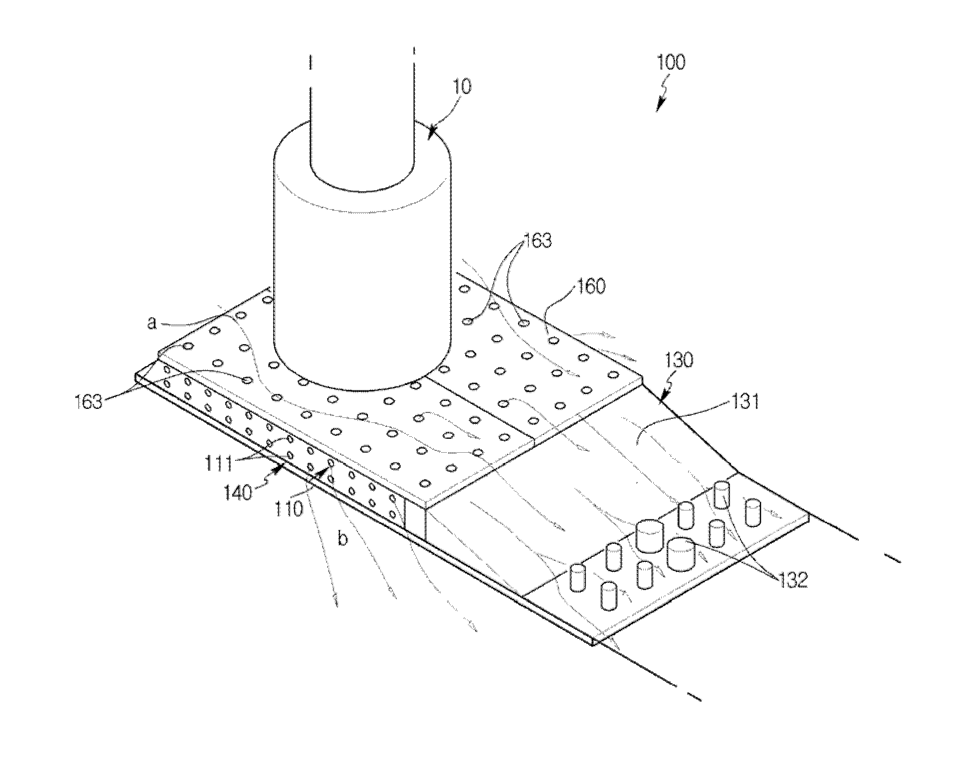
[0006]An objective of the present invention is that the scour preventive apparatus is installed near the ground of a pier foundation and collects a direct flow of a river directly rubbing the pier and an indirect flow flowing around the pier as one flow such that the flow of the river is stopped at a lower portion of the pier foundation and rub between an exterior circumference of the pier and the flow of the river can be prevented.
[0007]In addition, another objective of the present invention is that flowing speed of the river is changed to zero by the scour preventive apparatus installed at the ground of the pier so as to prevent erosion of the ground of the pier foundation.
[0008]Also, other objective of the present invention is that overload that may occur in the scour preventive apparatus maintaining the flow speed to be zero is minimized.
[0009]Further, other objective of the present invention is that the flow of the river passing through a flow hole and an upper surface of a blocking plate for preventing the overload of the scour preventive apparatus quickly flows to the rear of the pier foundation.
[0017]A flow separator abutting an exterior circumference of the pier foundation and having flow-separating surfaces being round and symmetrical to each other may further be included so as to prevent the fluid from rubbing the pier foundation directly.

Problems solved by technology

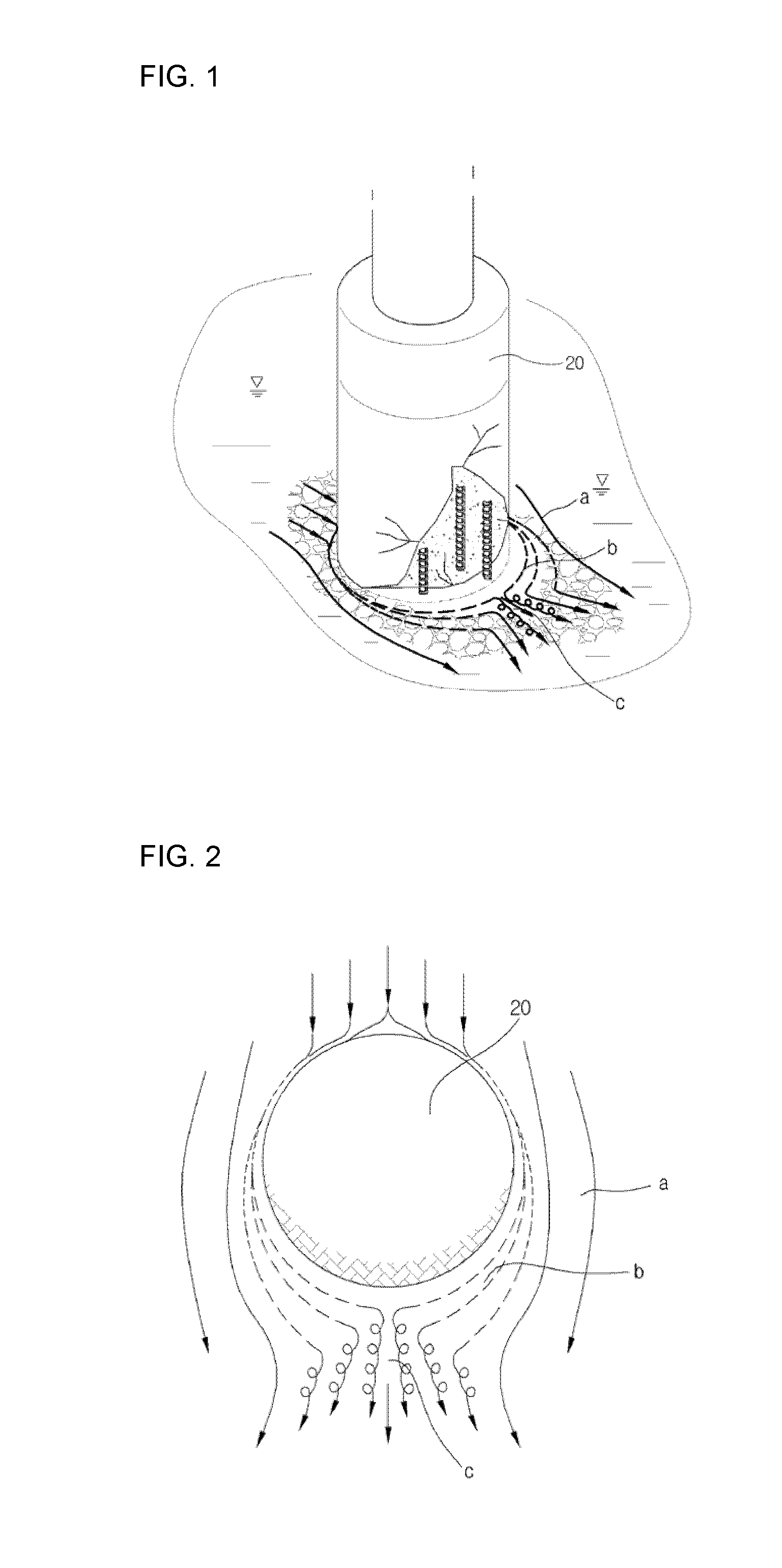
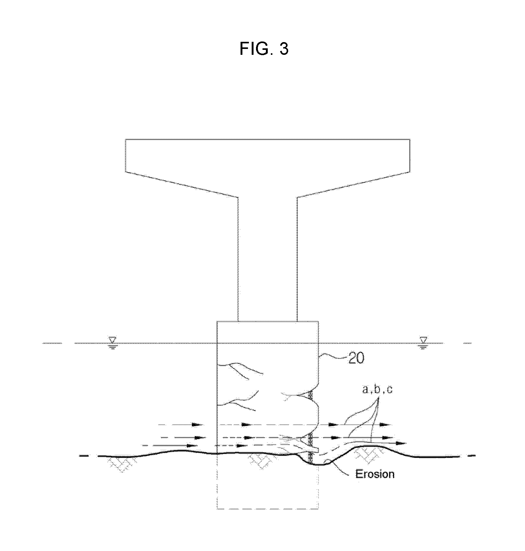
Strength of the foundation 20 is weakened by such phenomena, and this becomes causes of collapse of the bridge.

Method used


Image

  • Scour preventive apparatus for pier foundation
  • Scour preventive apparatus for pier foundation
  • Scour preventive apparatus for pier foundation

Examples


Embodiment Construction

[0030]Hereinafter, an exemplary embodiment of the present invention will be described in detail with reference to the attached drawings.

[0031]Firstly, it is kept in mind that the same constituent elements or components will be represented by the same reference numerals in the drawings. When explaining the present invention, a detailed description related to well-known functions or components will be omitted so as to prevent the spirit of the present invention from being obscured.

[0032]FIG. 4 is a perspective view showing an installed state of a scour preventive apparatus according to an exemplary embodiment of the present invention at a pier foundation. FIG. 5 is a front view showing an installed state of a scour preventive apparatus according to an exemplary embodiment of the present invention at a pier foundation, and FIG. 6 is an enlarged front view showing an installed state of a scour preventive apparatus according to an exemplary embodiment of the present invention at a pier f...


PUM


Abstract

A scour preventive apparatus for a pier foundation according to an exemplary embodiment of the present invention is the scour preventive apparatus for a pier foundation supporting load of the bridge, and may include a cover plate covering the pier foundation and formed of a plurality of holes, a first flow guide plate having a side connected to a surface of the cover plate, disposed apart from the pier foundation by a predetermined distance, and formed of a plurality of first flow holes, a second flow guide plate having a side connected to the surface of the cover plate, disposed apart from the pier foundation by the predetermined distance, and formed of a plurality of second flow holes, and a blocking plate connecting the first flow guide plate with the second flow guide plate and blocking a flow of fluid, wherein the first flow guide plate and the second flow guide plate are symmetrical to each other with respect to the pier foundation.

Description

TECHNICAL FIELD[0001]The present invention relates to a scour preventive apparatus for a pier foundation.BACKGROUND ART[0002]Generally, a bridge is installed at a river, a lake, and so on and means a high-level structure which vehicles or people can cross. The bridge is largely divided into an upper portion and a lower portion. The upper portion of the bridge is a part directly supporting load of the vehicles or the people, and includes an upper floor system and a mold. The lower portion of the bridge transmits the load of the upper portion to the ground, and includes an abutment, a pier, and a foundation (pile foundation, caisson foundation, and so on).[0003]At this time, bridge scour occurs at the foundation or the pier by the flowing fluid. Scour means the phenomena that a river bed or a river bank caves in by the fluid, and occurs in a case that amount of earth and sand removed from the foundation which is the lower portion of the bridge is larger than that of earth and sand dep...

Claims


Application Information

Patent Timeline
IPC IPC(8): E01D19/02
CPCE01D19/02E02D5/60E02B17/0017E02B1/00E02D19/04E01D22/00
Inventor JO, DEOK-RAE
Owner JO DEOK RAE
Learn More