Integratable efficient switching down converter

a converter and integrated circuit technology, applied in the field of power supplies, can solve the problems of generating large amounts of heat, and consuming more power in the circuit operating at higher frequencies, and reducing the operating voltage of the integrated circui

Active Publication Date: 2011-01-27
MARVELL ASIA PTE LTD
View PDF6 Cites 51 Cited by
  • Summary
  • Abstract
  • Description
  • Claims
  • Application Information

AI Technical Summary

Benefits of technology

[0008]The supply switching element includes a first supply terminal, a second supply terminal and a supply control terminal. The first supply terminal is electrically connected to the supply node. The supply control terminal receives a first control signal. The supply control terminal controls the resistance between the first supply terminal and the second supply terminal.
[0009]The top switching element includes a first top terminal, a second top terminal and a top control terminal. The first top terminal is electrically connected to the second supply terminal. The top control terminal receives a second control signal. The top control terminal controls the resistance between the first top terminal and the second top terminal.
[0010]The bottom switching element includes a first bottom terminal, a second bottom terminal and a bottom control terminal. The first bottom terminal is electrically connected to the second top terminal. The bottom control terminal receives a third control signal. The bottom control terminal controls the resistance between the first bottom terminal and the second bottom terminal.

Problems solved by technology

However, circuits operating at higher frequencies typically consume more power and generate higher amounts of heat.
Dissipating large amounts of heat from small circuit areas can often be difficult.
Lowering the operating voltage of integrated circuits can introduce new sets of problems, such as effective power distribution across the chip due to resistive losses.

Method used


Image

  • Integratable efficient switching down converter
  • Integratable efficient switching down converter
  • Integratable efficient switching down converter

Examples


Embodiment Construction

[0030]The present invention is described with reference to embodiments of the invention. Throughout the description of the invention reference is made to FIGS. 1-11.

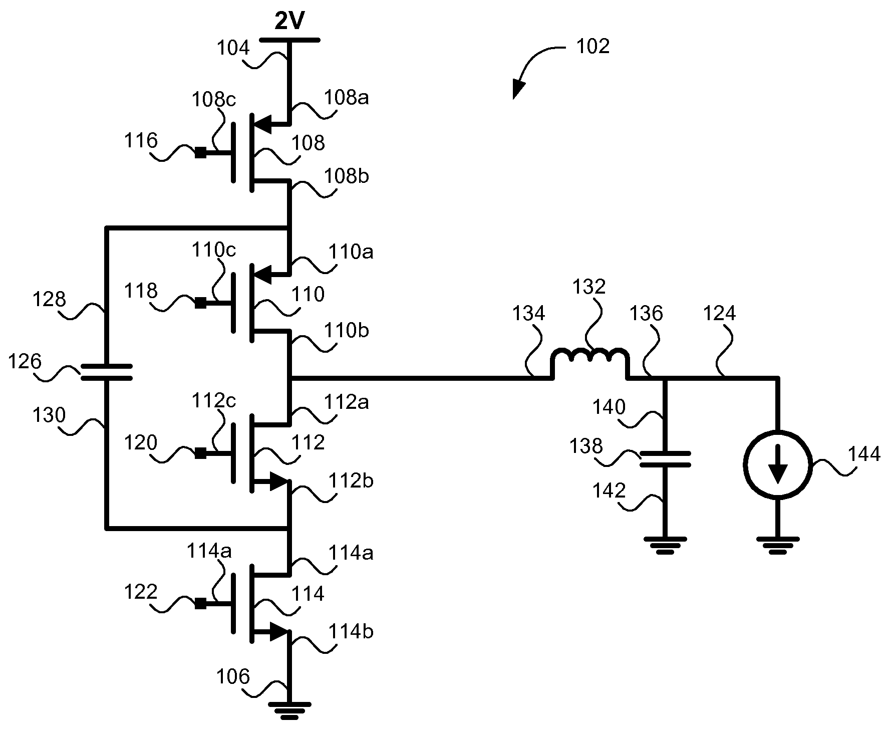
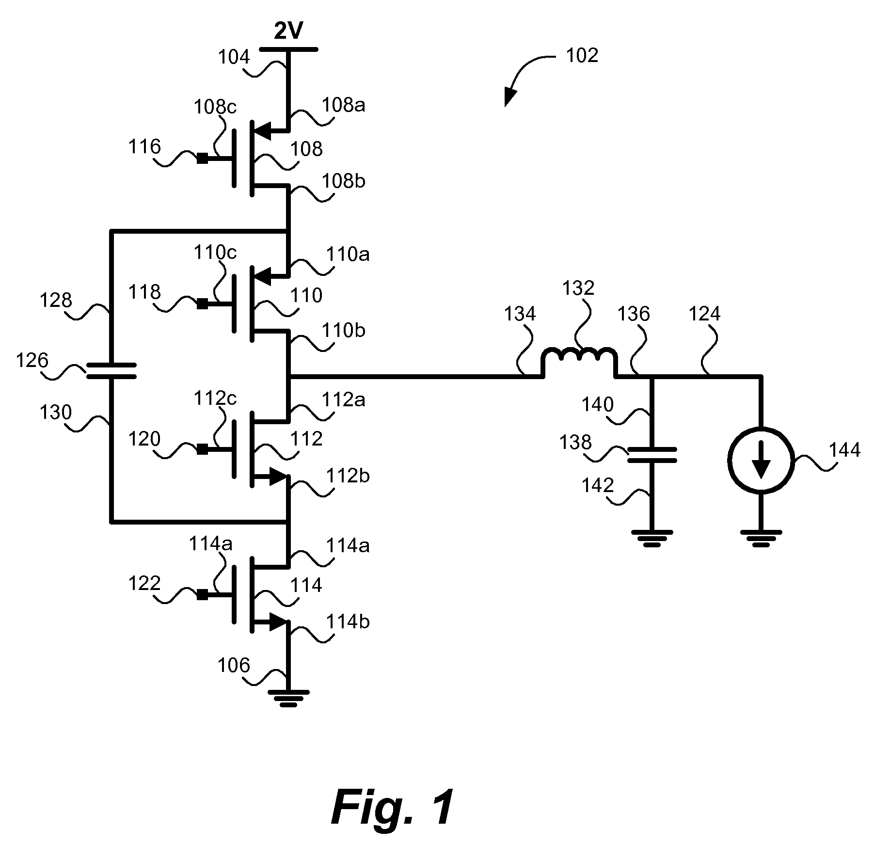
[0031]Turning to FIG. 1, an example of a voltage down converter circuit 102 contemplated by the present invention is shown. The voltage converter circuit 102 can be integrated in a chip to allow for efficient power distribution to various chip circuits.

[0032]The voltage converter circuit 102 includes a supply node 104 receiving a supply voltage. For illustration purposes, the supply voltage is shown to be two volts. It is noted that the actual supply voltage is dictated by design requirements and is not limited to a specific value. The circuit also includes a ground node 106 receiving a ground (zero) voltage.

[0033]The voltage converter circuit 102 includes four stacked switching elements 108, 110, 112 and 114. Each switching element contains a first terminal, a second terminal and a control terminal. The control terminal...


PUM


Abstract

A converter circuit and methods for operating the same. The converter circuit includes a supply voltage, a capacitor, an inductor, and four stacked switching elements. Each switching element is adjustable from a low resistance state to a high resistance state by a control signal. The inductor outputs current to a circuit load. The circuit may be operated in a first mode such that the output is adjustable between the supply voltage and half the supply voltage. Alternatively, in a second mode of operation, the output is adjustable from half the supply voltage to a ground voltage.

Description

BACKGROUND OF THE INVENTION[0001]1. Field of the Invention[0002]The present invention relates to power supplies and, more particularly, a down converter circuit and methods for operating the same.[0003]2. Description of Background[0004]Chip manufactures often look for ways to increase the functionality delivered by their integrated circuits. One way of increasing functionality is to operate integrated circuits at higher frequencies. However, circuits operating at higher frequencies typically consume more power and generate higher amounts of heat. Dissipating large amounts of heat from small circuit areas can often be difficult.[0005]One method of decreasing the amount of heat generated by an integrated circuit is to lower the operating voltage of the circuit. Lowering the operating voltage of integrated circuits can introduce new sets of problems, such as effective power distribution across the chip due to resistive losses.[0006]One solution for efficient the power distribution is t...

Claims


Application Information

Patent Timeline
Patent Type & Authority Applications(United States)
IPC IPC(8): G05F1/10
CPCH02M3/158
Inventor CARPENTER, GARY D.JI, BRIAN L.KIM, WONYOUNG
Owner MARVELL ASIA PTE LTD
Why Eureka
Try Eureka