
Gesture recognition method and touch system incorporating the same

a gesture recognition and touch technology, applied in the field of touch systems, can solve the problems of increasing system cost at the same time, not being able to correctly calculate the two dimensional coordinates of each finger,

Inactive Publication Date: 2011-01-27
PIXART IMAGING INC
View PDF8 Cites 31 Cited by
  • Summary
  • Abstract
  • Description
  • Claims
  • Application Information

AI Technical Summary

Benefits of technology

[0014]Since the gesture recognition method of the present invention and a touch system incorporating the same may perform gesture recognition according to a single pointer, miscalculation of the coordinates of a plurality of pointers from blocking each other can then be avoided.

Problems solved by technology

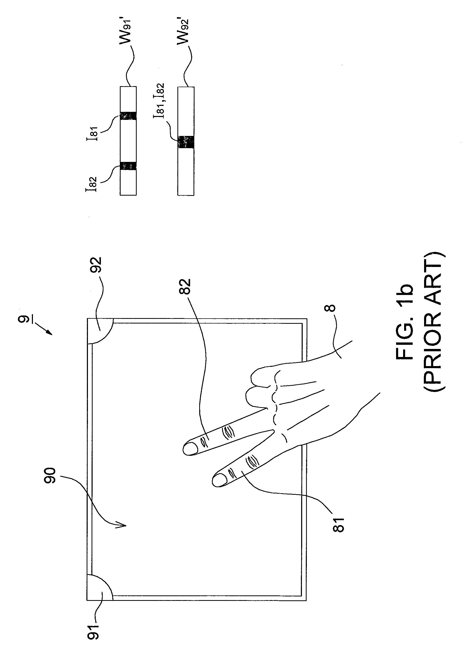
Accordingly, it is not possible to correctly calculate the two dimensional coordinates of every finger in some circumstances.
Although this problem can be solved by installing additional cameras, the system cost will be increased at the same time.

Method used


Image

  • Gesture recognition method and touch system incorporating the same
  • Gesture recognition method and touch system incorporating the same
  • Gesture recognition method and touch system incorporating the same

Examples


first embodiment

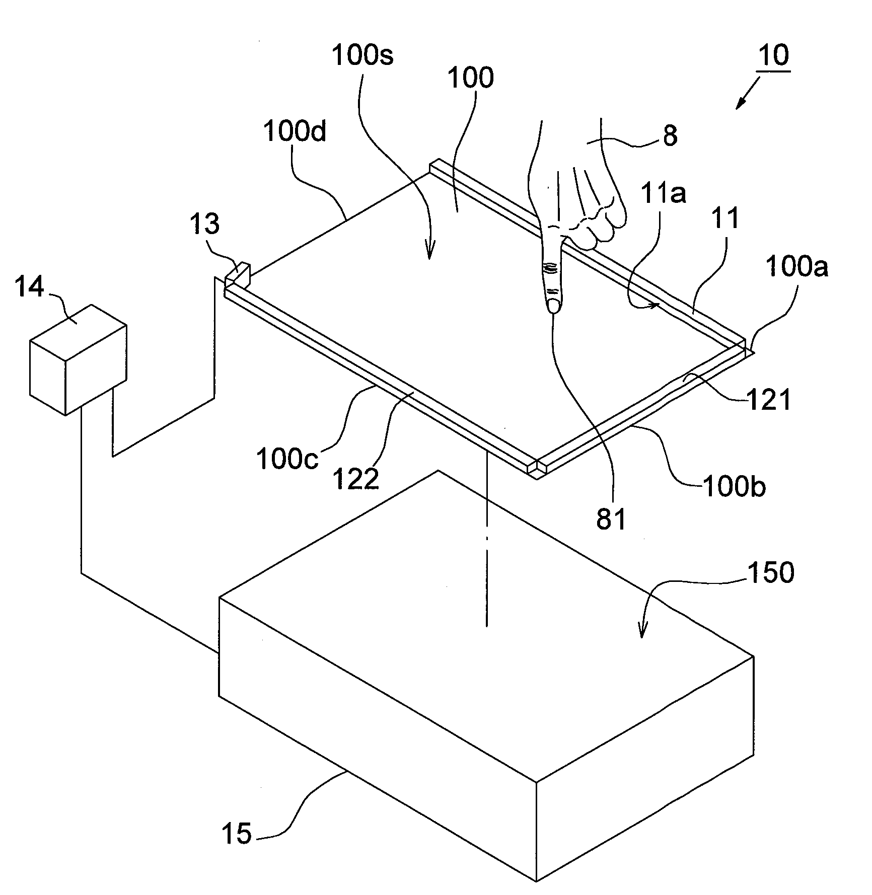
[0037]Please refer to FIG. 3, it shows an upper view of the touch system 10 according to the first embodiment of the present invention. In this embodiment, the illumination unit 11 is a passive light source (e.g. a reflecting component) and has a reflecting surface 11a facing the third side 100c of the plate 100. Accordingly, the first light source 121 may map a second mirror image 121′ relative to the reflecting surface 11a; the second light source 122 may map a third mirror image 122′ relative to the reflecting surface 11a; and the fourth side 100d of the plate 100 may map a fourth mirror image 100d′ relative to the reflecting surface 11a, wherein the illumination unit 11, the first light source 121, the second light source 122 and the fourth side 100d of the plate 100 together define a real space RS; and the illumination unit 11, the second mirror image 121′, the third mirror image 122′ and the fourth mirror image 100d′ together define a virtual space IS.

[0038]The image sensor 13...

second embodiment

[0041]Please refer to FIGS. 5a and 5b, FIG. 5a shows a block diagram of the touch system 10′ according to the second embodiment of the present invention; FIG. 5b shows a schematic diagram of image windows captured by the two image sensors 13, 13′ shown in FIG. 5a. The differences between this embodiment and the first embodiment are in that the illumination unit 11′ herein is an active light source and the touch system 10′ includes two image sensors 13 and 13′.

[0042]In the second embodiment, the touch system 10′ includes a plate 100, an illumination unit 11′, a first light source 121, a second light source 122, two image sensors 13, 13′ and a processing unit 14. The illumination unit 11′ is disposed at the first side 100a on the plate surface 100s and preferably illuminates toward the third side 100c of the plate 100. The first light source 121 is disposed at the second side 100b on the plate surface 100s and preferably illuminates toward the fourth side 100d of the plate 100. The se...


PUM


Abstract

A gesture recognition method for a touch system includes the steps of: capturing images looking across a plate surface with at least one image sensor; processing the images to determine a contact state variation of a single pointer on the plate surface; and recognizing whether a relative variation between the single pointer and the plate surface matches a predetermined gesture when the contact state variation is larger than a threshold. The present invention further provides a touch system.

Description

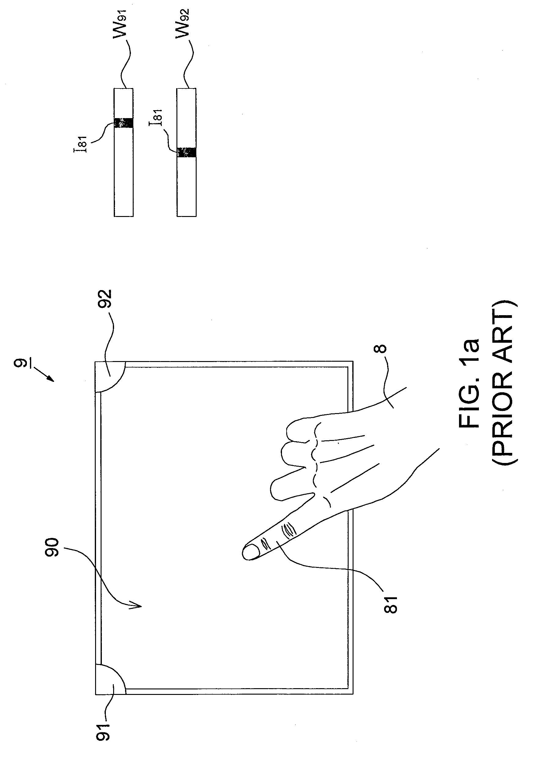
CROSS REFERENCE TO RELATED APPLICATION[0001]This application claims the priority benefit of Taiwan Patent Application Serial Number 098124545, filed on Jul. 21, 2009, the full disclosure of which is incorporated herein by reference.BACKGROUND[0002]1. Field of the Invention[0003]This invention generally relates to a touch system and, more particularly, to a gesture recognition method and a touch system incorporating the same.[0004]2. Description of the Related Art[0005]Please refer to FIGS. 1a and 1b, they show operational schematic diagrams of a conventional touch system 9, which includes a touch plate 90 and at least two cameras 91 and 92. Field of views of the cameras 91 and 92 encompass the whole touch plate 90 for capturing images looking across a surface of the touch plate 90. When a user 8 contacts the touch plate 90 with one finger 81, the cameras 91 and 92 respectively capture image windows W91 and W92 containing a shadow I81 associated with the tip of the finger 81. A proce...

Claims


Application Information

Patent Timeline
Patent Type & Authority Applications(United States)
IPC IPC(8): G06F3/041G06F3/01
CPCG06F3/04883G06F3/0428
Inventor LIN, CHO YIHSU, YAO CHING
Owner PIXART IMAGING INC
Learn More