Shape-Transforming Implant Device

a technology of implant devices and sternal closures, applied in the field of surgical devices, can solve the problems of significant sternal closure complication rate and disadvantages of using stainless steel wires

Inactive Publication Date: 2011-01-27
INTELIFUSE
View PDF5 Cites 28 Cited by
  • Summary
  • Abstract
  • Description
  • Claims
  • Application Information

AI Technical Summary

Benefits of technology

[0008]One aspect of the present invention is a shape-transforming implant device for joining and holding in place a severed sternum. The device includes a bridge portion, two or more legs extending from the bridge portion, shoulder portions, and feet portions. The bridge portions have a thickness that is sized such that it can be cut with a pin cutter. The two or more legs extend from the bridge portion at a first angle when the bridge and the two or more legs are at a first temperature. The shoulder portions are defined by a first angle between the bridge portion and the two or more legs and define a transition from the bridge portion to the two or more legs. The feet portions are at an end of the two or more legs. The end is opposite from the shoulder portions. Each of the feet portions include an inwardly angled portion that extends toward the remaining feet portions. The feet portions are configured to stabilize the device once it has been placed around the sternum and its shape transformed.

Problems solved by technology

Regardless of the method used, the complication rate of the sternal closure is significant.
Unfortunately, as mentioned above, there are disadvantages to using stainless steel wire.

Method used


Image

  • Shape-Transforming Implant Device
  • Shape-Transforming Implant Device
  • Shape-Transforming Implant Device

Examples


Embodiment Construction

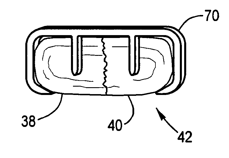
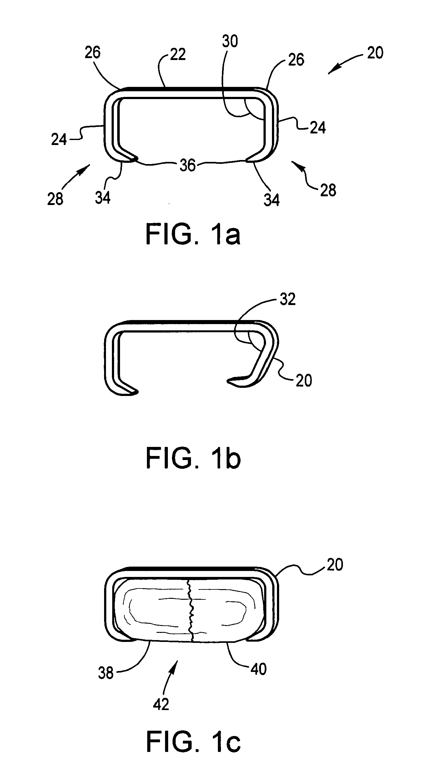
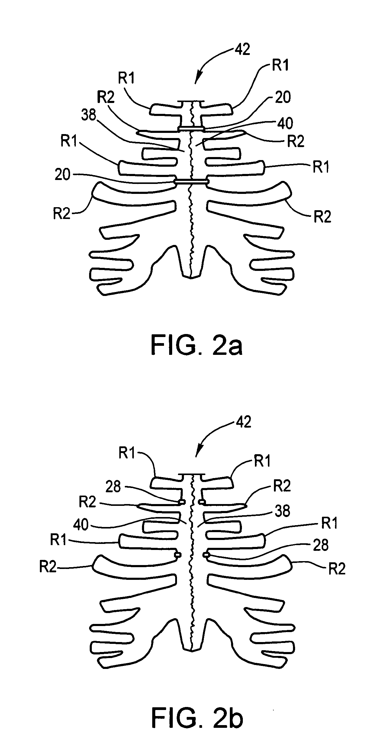
[0026]Referring now to the drawings in which like reference numerals indicate like parts, and in particular, to FIGS. 1-8, one aspect of the present invention is a shape-transforming implant device for joining and holding in place a severed sternum.

[0027]The shape-transforming implant device is typically formed from a shape memory material such those from a family of intermetallic materials named nitinol, an acronym for NIckel TItanium Naval Ordnance Laboratory. The properties of nitinol allow the material to exist in two stable phases. The lower temperature phase is referred to as the martensitic phase, due to its metallic structure being composed primarily of martensite. The higher temperature phase is referred to as the austenitic phase. Nitinol is an alloy composed primarily of nickel and titanium. By varying the percentage of nickel and titanium, different transition temperatures can be achieved. Transformation temperatures can be either below that of body temperature or slight...


PUM


Abstract

A shape-transforming implant device for joining and holding in place a severed sternum. The device includes a bridge portion, two or more legs extending from the bridge portion, shoulder portions, and feet portions. The bridge portions have a thickness that is sized such that it can be cut with a pin cutter. The two or more legs extend from the bridge portion at a first angle when the bridge and the two or more legs are at a first temperature. The shoulder portions are defined by a first angle between the bridge portion and the two or more legs and define a transition from the bridge portion to the two or more legs. The feet portions are at an end of the two or more legs that is opposite from the shoulder portions. Each of the feet portions include an inwardly angled portion that extends toward the remaining feet portions.

Description

BACKGROUND OF THE INVENTION[0001](1) Field of the Invention[0002]The present invention generally relates to surgical devices. In particular, the present invention is directed to methods and devices for joining and fusing a severed sternum.[0003](2) Description of the Related Art[0004]The sternum is a flat elongated bone, which forms the middle portion of the anterior wall of the thorax. Its upper end supports the clavicles and its sides attach the cartilage of the first seven pairs of ribs. The sternum articulates on either side with the clavicle and upper seven costal cartilages. The bone material of the sternum consists of an outer shell of cortical bone covering the less dense cancellous bone.[0005]While fractures of the sternum are not common, the sternum is cut or osteotomized, in a procedure called a stenotomy, to gain access to the organs of the chest, most commonly the heart. A partial sternotomy is a procedure in which a cut is made along the midline of the sternum and the ...

Claims


Application Information

Patent Timeline
Patent Type & Authority Applications(United States)
IPC IPC(8): A61B17/84
CPCA61B17/0642A61B17/823A61B2017/081A61B2017/0641A61B2017/00867
Inventor ASHMAN, RICHARD B.
Owner INTELIFUSE
Why Eureka
Try Eureka