Control device for internal combustion engine

a control device and internal combustion engine technology, applied in the direction of electric control, ignition automatic control, instruments, etc., can solve the problems of reducing the efficiency setting the increase of the demanded torque setting and the temporary decrease of the demand torque setting, etc., to increase the torque quickly, reduce the demand efficiency, and increase the operation in an overshoot manner

Active Publication Date: 2011-01-27
TOYOTA JIDOSHA KK
View PDF8 Cites 5 Cited by
  • Summary
  • Abstract
  • Description
  • Claims
  • Application Information

AI Technical Summary

Benefits of technology

[0004]The present invention has been made in view of the above circumstances. An object of the present invention is to provide a control device that is used with an internal combustion engine and capable of improving the responsiveness and controllability of torque generated by the internal combustion engine.
[0008]As the control device includes the above-described means for correcting the demanded efficiency, a demanded air amount increase caused by a rapid increase in the demanded torque is superimposed over a demanded air amount increase caused by a temporary decrease in the demanded efficiency when the demanded torque increases rapidly. Consequently, a temporary rapid increase occurs in the demanded air amount. As the operation amount of the intake actuator is calculated from the demanded air amount that has experienced a temporary rapid increase, the intake actuator operates in an overshoot manner. When the intake actuator operates in an overshoot manner, the responsiveness of the amount of air taken into a cylinder improves, thereby improving the responsiveness of achieved torque to the demanded torque. At the same time, the ignition timing is retarded so as to suppress a torque overshoot that occurs due to a rapid increase in the intake air amount. This prevents the achieved torque from overshooting the demanded torque. In other words, the first aspect of the present invention not only improves the torque response of the internal combustion engine, but also provides adequate torque controllability.
[0010]When the degree of a temporary decrease in the demanded efficiency setting is increased in accordance with the degree of a rapid increase in the demanded torque setting or when the time of a temporary decrease in the demanded efficiency setting is increased in accordance with the degree of a rapid increase in the demanded torque setting, the degree of a temporary rapid increase in the demanded air amount increases due to a synergistic effect. It means that an increase in the degree of a rapid increase in the demanded torque setting will increase the scale of an overshoot manner operation of the intake actuator and improve the responsiveness of the amount of air taken into a cylinder. Therefore, a high torque-responsiveness can be obtained relative to a demand for rapid torque increase. On the other hand, when the degree of a rapid increase in the demanded torque setting is small, that is, when the scale of an overshoot manner operation of the intake actuator is small, the degree and the time of a temporary decrease in the demanded efficiency setting are decreased. This makes it possible to suppress the retard of ignition timing, which is unfavorable to fuel economy. Consequently, when the degree and the time of a temporary decrease in the demanded efficiency setting are determined in accordance with the degree of a rapid increase in the demanded torque setting, adequate torque response and fuel economy can be both maintained.
[0014]As the control device includes the above-described various means, a demanded air amount increase caused by a rapid increase in the demanded torque is superimposed over a demanded air amount increase caused by a temporary decrease in the demanded efficiency when a demand for rapid torque increase is detected. Consequently, a temporary rapid increase occurs in the demanded air amount. As the operation amount of the intake actuator is calculated from the demanded air amount that has experienced a temporary rapid increase, the intake actuator operates in an overshoot manner. When the intake actuator operates in an overshoot manner, the responsiveness of the amount of air taken into a cylinder improves, thereby improving the responsiveness of achieved torque to the demanded torque. At the same time, the ignition timing is retarded so as to suppress a torque overshoot that occurs due to a rapid increase in the intake air amount. This prevents the achieved torque from overshooting the demanded torque. In other words, the second aspect of the present invention not only improves the torque responsiveness of the internal combustion engine, but also provides adequate torque controllability.
[0016]When the degree of a temporary decrease in the demanded efficiency value is increased in accordance with the magnitude of the demand for rapid torque increase or when the time of a temporary decrease in the demanded efficiency value is increased in accordance with the magnitude of the demand for rapid torque increase, the degree of a temporary rapid increase in the demanded air amount increases due to the synergistic effect of a rapid increase in the demanded torque and a decrease in the demanded efficiency. It means that an increase in the magnitude of the demand for rapid torque increase will enlarge the scale of an overshoot manner operation of the intake actuator and improve the responsiveness of the amount of air taken into a cylinder. Therefore, a high torque-responsiveness can be obtained relative to a demand for rapid torque increase. On the other hand, when the magnitude of the demand for rapid torque increase is small, that is, when the scale of an overshoot manner operation of the intake actuator is small, the degree and the time of a temporary decrease in the demanded efficiency value are decreased. This makes it possible to suppress the retard of ignition timing, which is unfavorable to fuel economy. Consequently, when the degree and the time of a temporary decrease in the demanded efficiency value are determined in accordance with the magnitude of the demand for rapid torque increase, adequate torque response and fuel economy can be both maintained.

Problems solved by technology

However, a slight timing difference between the rapid increase in the demanded torque setting and the temporary decrease in the demanded efficiency setting is allowable as far as the later-described responsiveness of the intake air amount remains unaffected.

Method used


Image

  • Control device for internal combustion engine
  • Control device for internal combustion engine
  • Control device for internal combustion engine

Examples


first embodiment

[0033]A first embodiment of the present invention will now be described with reference to FIGS. 1 and 2.

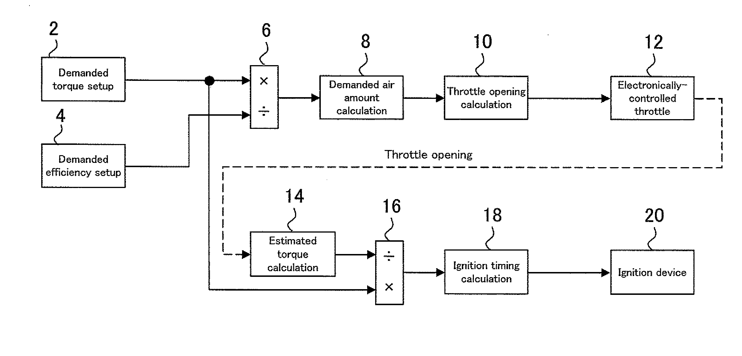
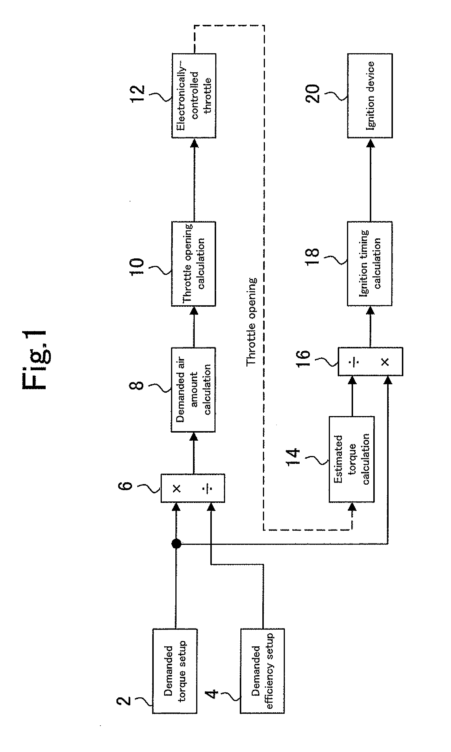
[0034]FIG. 1 is a block diagram illustrating the configuration of an internal combustion engine control device according to the first embodiment of the present invention. The control device according to the present embodiment is a control device for use with a spark-ignition internal combustion engine. The control device according to the present embodiment controls the torque of an internal combustion engine by operating an ignition device 20 and an electronically-controlled throttle (hereinafter simply referred to as the throttle) 12, which serves as an intake actuator.

[0035]The control device according to the present embodiment includes a demanded torque setup section 2, which sets a demanded torque value for the internal combustion engine. The demanded torque setup section 2 sets a demanded torque in consideration of not only a torque demand from a driver, which is calculated f...

second embodiment

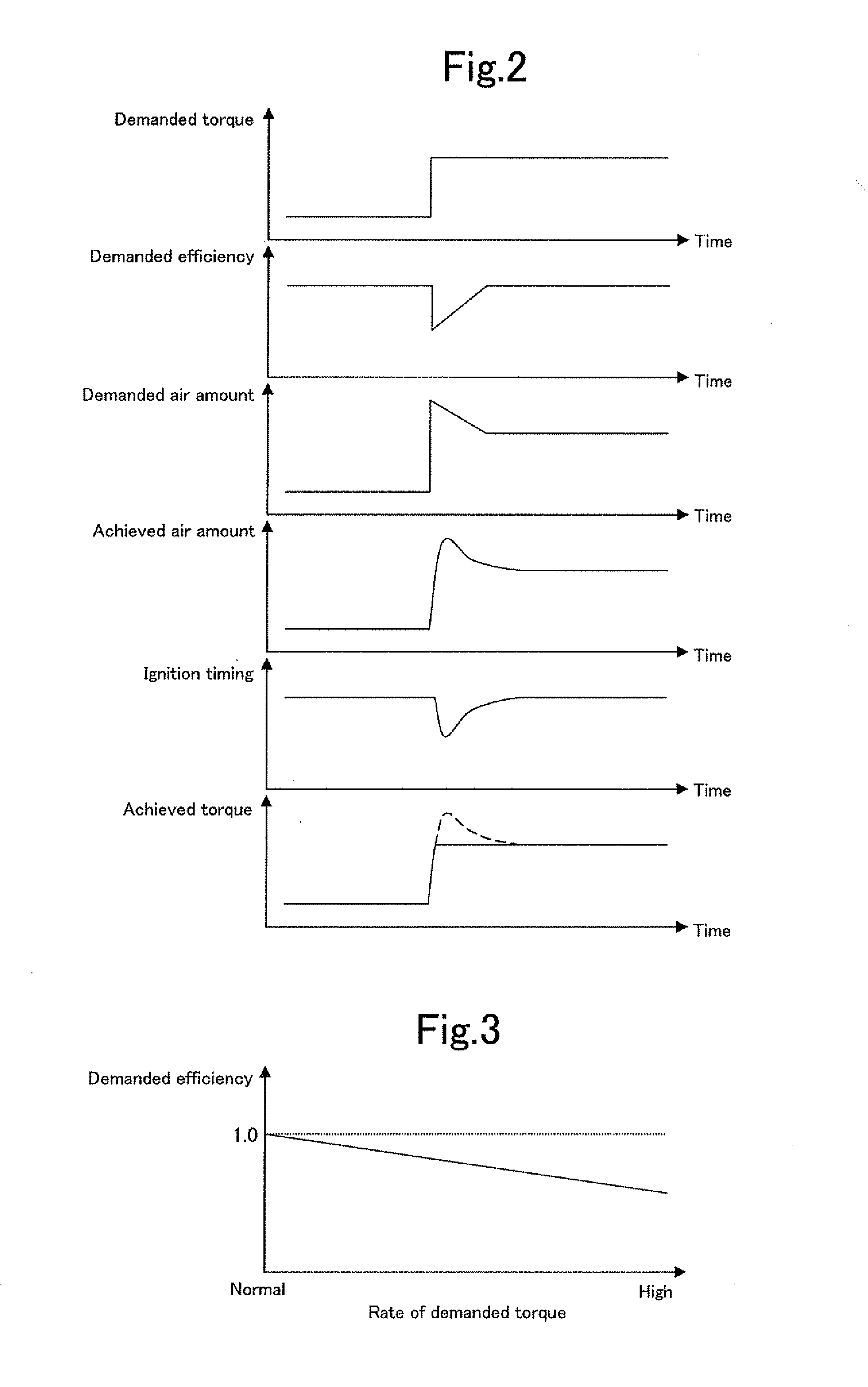
[0056]A second embodiment of the present invention will now be described with reference to FIG. 3.

[0057]The overall configuration of the control device according to the second embodiment is illustrated in the same block diagram of FIG. 1 as for the first embodiment. The control device according to the second embodiment differs from that according to the first embodiment in the function of the “means for correcting the demanded efficiency,” which is included in the demanded efficiency setup section 4.

[0058]When the demanded torque setting is rapidly increased, the demanded efficiency setup section 4 according to the second embodiment also temporarily decreases the demanded efficiency setting below the last setting at the timing when the demanded torque setting is rapidly increased. However, the second embodiment differs from the first embodiment in the setup of an amount by which the demanded efficiency setting is temporarily decreased. The second embodiment determines the amount of ...

third embodiment

[0062]A third embodiment of the present invention will now be described with reference to FIG. 4.

[0063]FIG. 4 is a block diagram illustrating the configuration of an internal combustion engine control device according to the third embodiment of the present invention. Elements that are shown in FIG. 4 and identical with those of the control device according to the first embodiment shown in FIG. 1 are assigned the same reference numerals as their counterparts. As is obvious from comparison between FIGS. 1 and 4, the control device according to the third embodiment differs from the control device according to the first embodiment in that the demanded torque and demanded efficiency are supplied from the outside of the control device. The third embodiment assumes that the demanded torque and demanded efficiency are supplied from a power train manager (hereinafter referred to as the PTM) (not shown), which provides integrated control over the entire drive system of the vehicle. The contro...


PUM


Abstract

A control device that is used with an internal combustion engine to improve both the response and controllability of torque generated by the internal combustion engine. The control device calculates an operation amount of an intake actuator in accordance with a demanded air amount. The control device then calculates a torque that is generated when the intake actuator is operated by the calculated operation amount at a predetermined ignition timing setting, and calculates an ignition timing retard amount that is necessary to achieve a demanded torque in accordance with the difference between the calculated torque and the demanded torque. The control device ensures that the demanded torque and a demanded efficiency are both reflected in the demanded air amount.

Description

TECHNICAL FIELD[0001]The present invention relates to a control device for an internal combustion engine, and more particularly to a control device that is used with an internal combustion engine and capable of exercising torque control by operating an intake actuator for adjusting an intake air amount and by making ignition timing adjustments.BACKGROUND ART[0002]A technology disclosed in JP-A-2007-132203 effectively improves the responsiveness of torque generated by an internal combustion engine. When the amount of torque control for generating a target torque is to be calculated, the disclosed technology compensates the difference between an estimated torque, which is estimated from a target torque control amount, and a target torque for a control response lag. Next, the obtained difference, which is now compensated for the control response lag, is added to the target torque. A torque control amount is then calculated from the resulting target torque. This conventional technology ...

Claims


Application Information

Patent Timeline
Patent Type & Authority Applications(United States)
IPC IPC(8): F02D28/00
CPCF02D37/02F02D41/0002F02D41/10F02D41/1497F02D2200/1004Y02T10/42F02D2250/21F02D2250/22F02P5/045F02P5/1504Y02T10/46F02D2250/18Y02T10/40
Inventor SOEJIMA, SHINICHIKATO, NAOTOKAWAI, KEISUKE
Owner TOYOTA JIDOSHA KK
Why Eureka
Try Eureka