
Eddy current for the characterization of broached tube support plate blockage

Inactive Publication Date: 2011-01-27
AREVA NP INC
View PDF6 Cites 19 Cited by
  • Summary
  • Abstract
  • Description
  • Claims
  • Application Information

AI Technical Summary

Benefits of technology

[0010]An object of the invention is to provide measured values from a bobbin eddy current examination of steam generator tubing to calculate the degree of flow restriction, “clogging,” or “blockage,” at each of the TSP flow regions, and subsequently,

Problems solved by technology

This deposition collects and builds up as sludge patches about broached openings of TSP 58, particularly on the free tube heat transfer surface which reduces the efficiency and the blockage within the support flow holes which acts as an impediment to the flow of feedwater and the water / steam mixture in the upper parts of the tube bundle as the water converts to steam.
This current practice requires unacceptable amounts of time and exposes personnel to large amounts of accumulated radioactive dose.
If a steam generator does not provide access ports for visual inspection tooling between each pair of TSP, the visual examination is limited to accessible areas for the uppermost TSP.
Consequently, a complete examination of the population of TSP flow regions is not possible and subsequent analysis of the effect of observed flow restriction of steam generator operational parameters would be subject to large uncertainties.
A proposed application of a flux leakage eddy current method presupposes the existence of a specific deposition formation “webbing” as the primary and substantial cause of TSP flow region clogging within the steam generator.
This application does not provide a process to relate the collective measured results of the collective TSP flow regions to any of the critical operational parameters for the steam generator.
While the proposed method may yield a relative pattern of clogging for a single or set of tube support plates, the application does not address any specific use of these results to ascertain the operational characteristics of the steam generator.

Method used


Image

  • Eddy current for the characterization of broached tube support plate blockage
  • Eddy current for the characterization of broached tube support plate blockage
  • Eddy current for the characterization of broached tube support plate blockage

Examples


Embodiment Construction

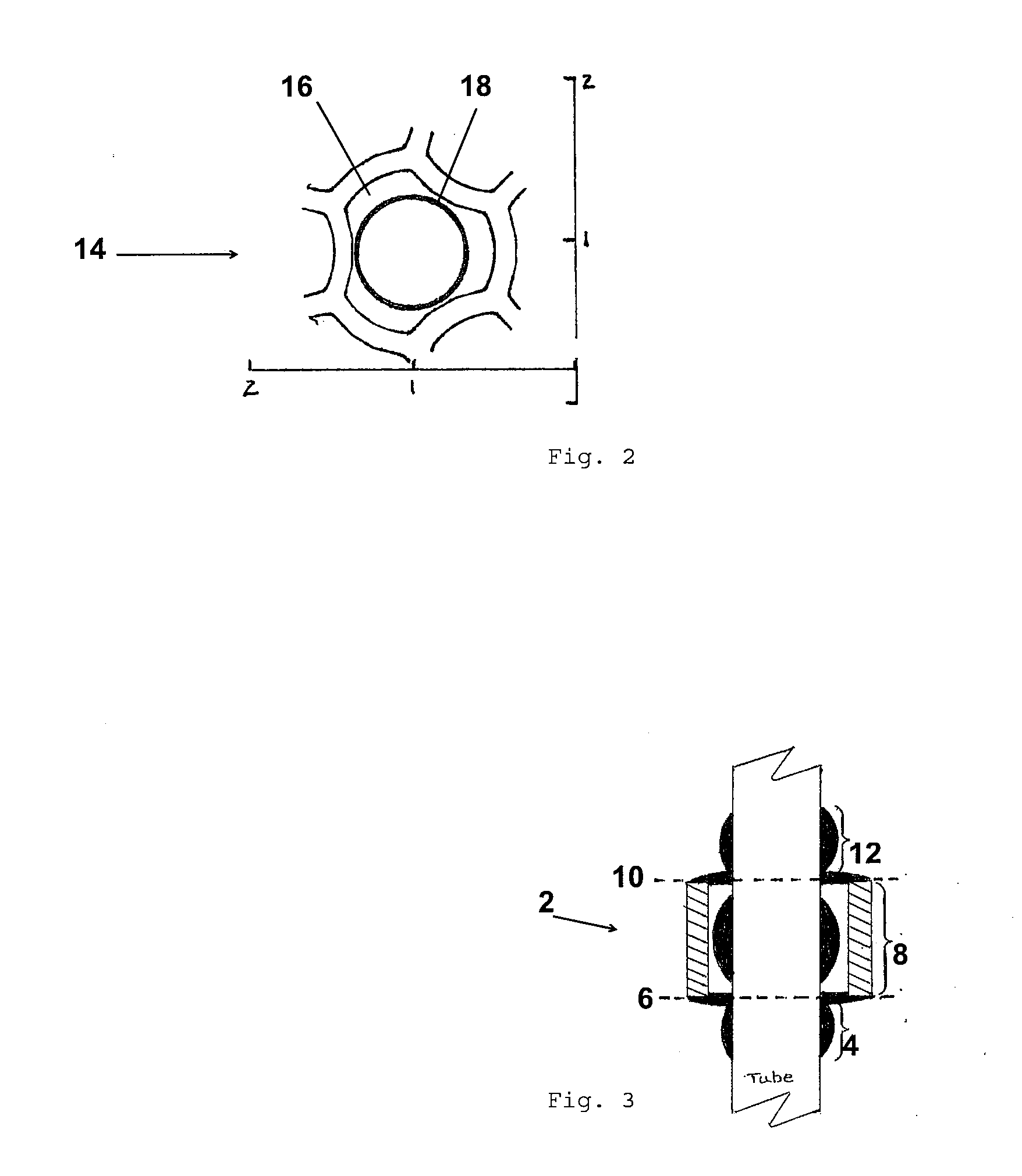
[0019]Bobbin coil eddy current data is used to make calibrated quantitative measurements of deposition around and within the support. A bobbin coil eddy current probe is used to sense changes in the quantity of material deposited in and around the support plate as the probe is drawn axially through the tube. Various alterations in the eddy current TSP signal response are detected during the analysis of the eddy current data for open tube surface deposition and tubing flaws. Five separate measurements to characterize the deposition in the TSP region may be performed. Although these measured values may be used to determine the deposit loading within each tube support intersection, a more appropriate use has been found to determine the flow restriction present at each tube support intersection and subsequently the collective effect of the flow restriction of the population of tube intersections on several operational concerns for the steam generator.

[0020]FIG. 3 shows a section of the ...


PUM


Abstract

A method for determining tube support plate blockage of a steam generator includes the following steps: measuring at least five different eddy current values per tube support intersection; calculating a nominal clean fit radius of flow hole; determining a center signal response; converting the center signal response to a deposit thickness; determine an edge reduction; converting the edge reduction to an edge thickness; calculating the resulting flow hole radius; verifying the reasonableness of the resulting flow hole radius; and determining a virtual calibration range.

Description

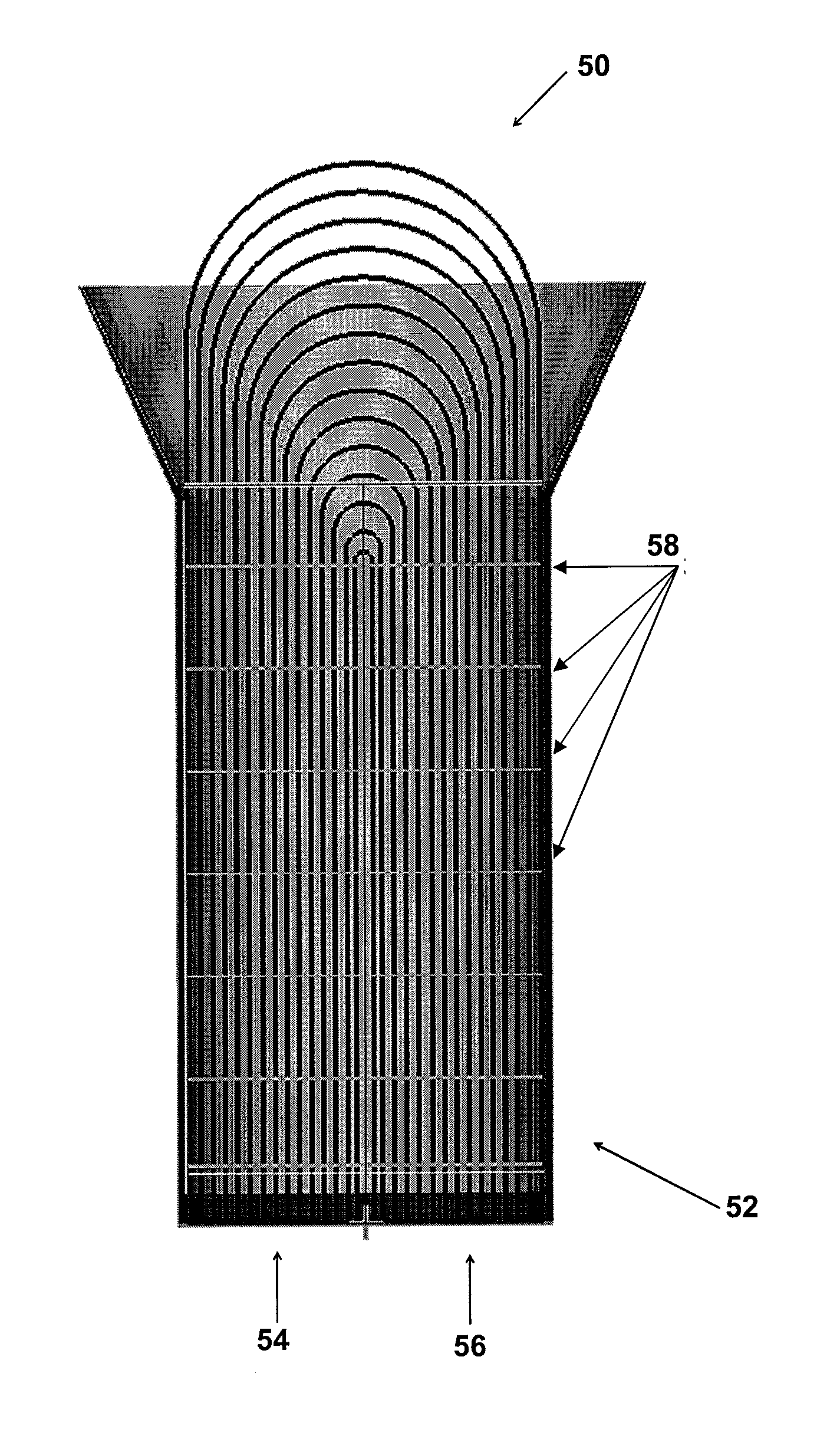
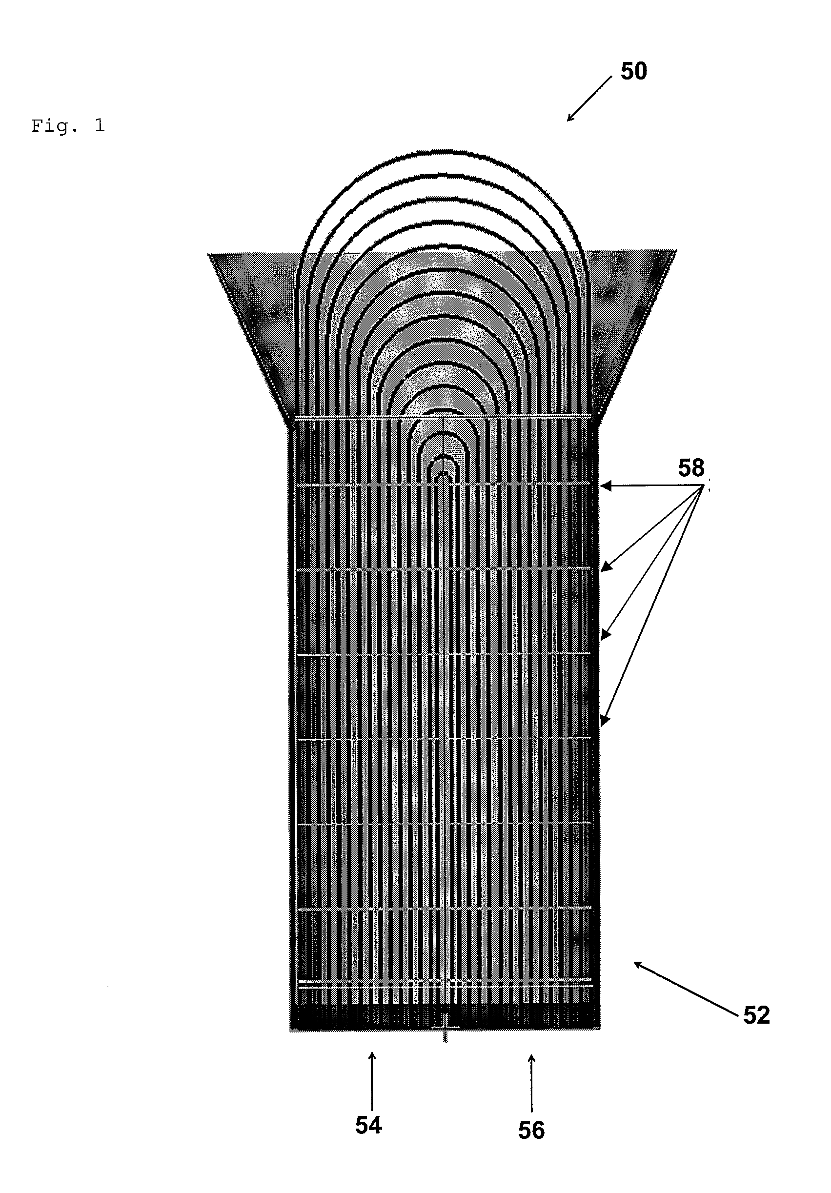
[0001]Priority to U.S. Provisional Patent Application Ser. No. 61 / 271,691 filed Jul. 24, 2009, is claimed, the entire disclosure of which is hereby incorporated by reference.[0002]The present invention relates generally to tube support plates of steam generators.BACKGROUND[0003]FIG. 1 shows a nuclear steam generator 52 which comprises a plurality of U-shaped tubes disposed within its shell to form tube bundles 50. Tube bundles 50 typically contain thousands of generator tubes. Tube sheets are provided for supporting the tubes at the ends opposite the U-shaped curvature. A primary fluid is heated in the reactor core through circulation and enters steam generator 52 through a primary inlet 54 fluid nozzle where it is distributed by upper tube sheet through the generator tubes and collected at the lower tube sheet. The fluid then flows through a primary fluid outlet 56 nozzle to the remainder of the reactor system. A feedwater stream is also introduced into steam generator 52 secondary...

Claims


Application Information

Patent Timeline
IPC IPC(8): G06F19/00G01F1/00
CPCB24B49/105G01N27/9046F22B37/003
Inventor GRIFFITH, JOHN C.WYATT, JOSEPH R.POP, MIHAI G.M.FLECK, JEFFREY M.
Owner AREVA NP INC
Learn More