Scr catalyst heating control

a technology of catalyst heating and catalyst, which is applied in the direction of electrical control, exhaust treatment electric control, separation process, etc., can solve the problems of ammonia slippage from the catalyst, increase of particulate emissions, etc., and achieve the effect of increasing the temperature of the scr catalyst and increasing the emission of nitrogen oxide (nox)

Active Publication Date: 2011-02-03
FORD GLOBAL TECH LLC
View PDF11 Cites 33 Cited by
  • Summary
  • Abstract
  • Description
  • Claims
  • Application Information

AI Technical Summary

Benefits of technology

The patent text describes an emission control system for diesel vehicles that includes a selective catalytic reduction (SCR) catalyst and a diesel particulate filter (DPF). When the DPF is used, thermal regeneration is employed to clean the filter by increasing the temperature and burning soot that has collected in the filter. As the temperature of the DPF increases, the temperature of the SCR catalyst may also increase. Ammonia that is used as a reductant in the catalyst may be desorbed from the SCR catalyst when the temperature increases resulting in ammonia slip from the catalyst. The slipped ammonia may exit the tailpipe and enter the atmosphere and/or the ammonia may be oxidized when passing through the DPF to formNOx, thus increasing nitrogen oxide (NOx) emissions. The technical effect of the patent text is to provide a solution to reduce NOx emissions in diesel vehicles that use a DPF and an SCR catalyst.

Problems solved by technology

The technical problem addressed in this patent is the reduction of ammonia slip during regeneration of a diesel particulate filter in a diesel aftertreatment system, which can increase nitrogen oxide (NOx) emissions. The inventors have devised a method to adjust the amount of stored ammonia in the selective catalytic reduction (SCR) catalyst and initiate regeneration of the catalyst when the desired amount of stored ammonia is reached, to control heating for regeneration of the DPF and reduce ammonia slip and NOx emissions.

Method used


Image

  • Scr catalyst heating control
  • Scr catalyst heating control
  • Scr catalyst heating control

Examples


Embodiment Construction

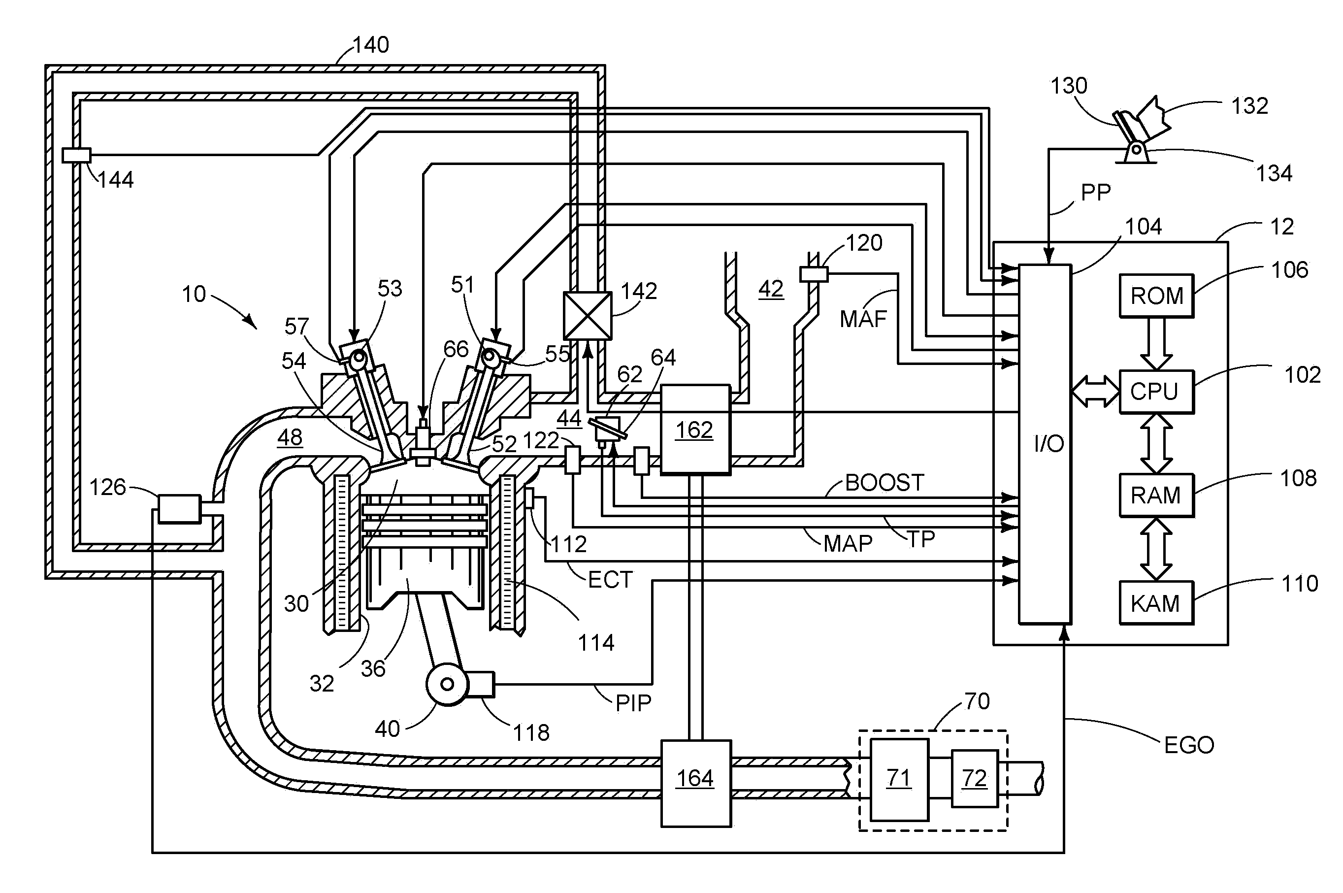
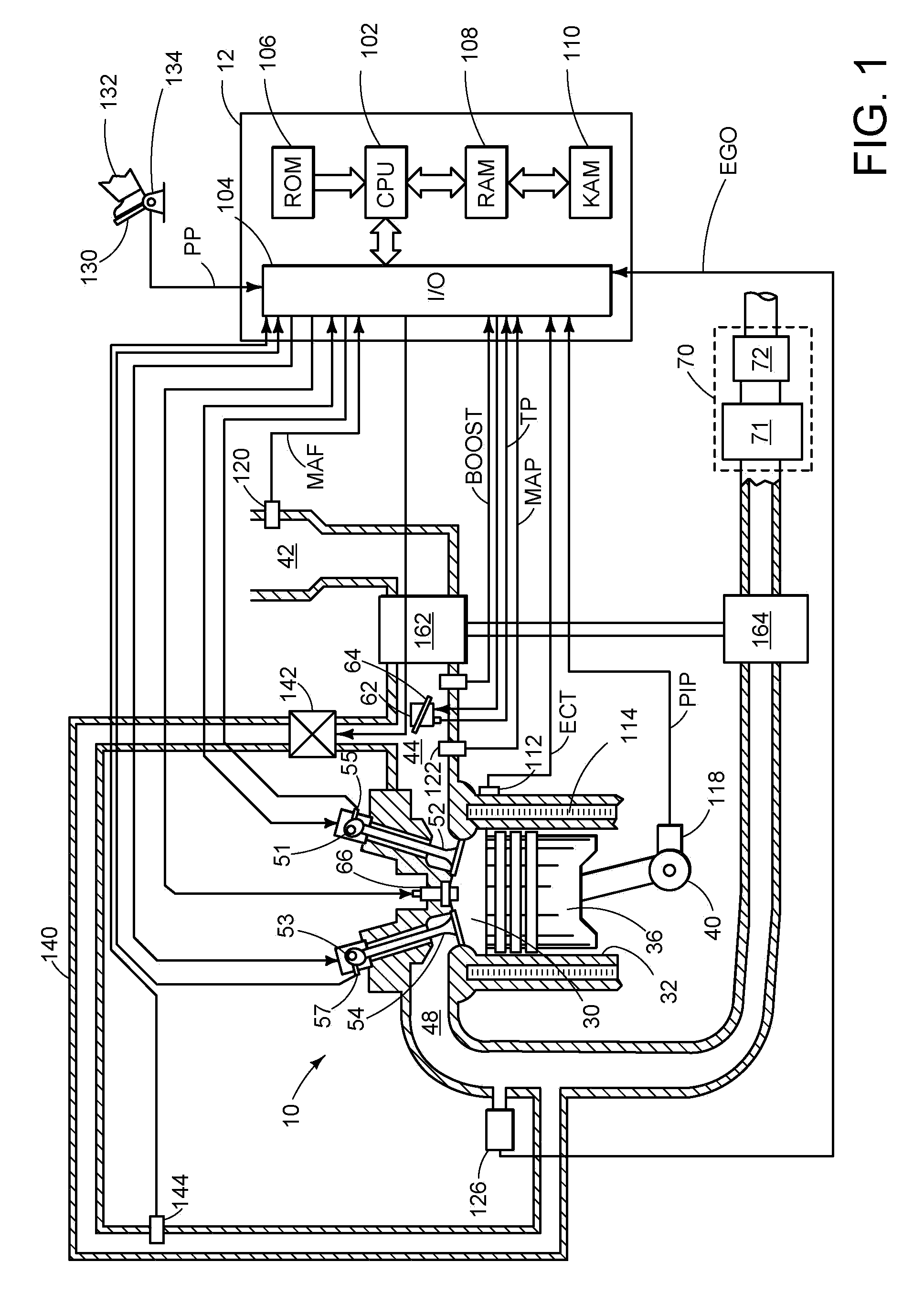
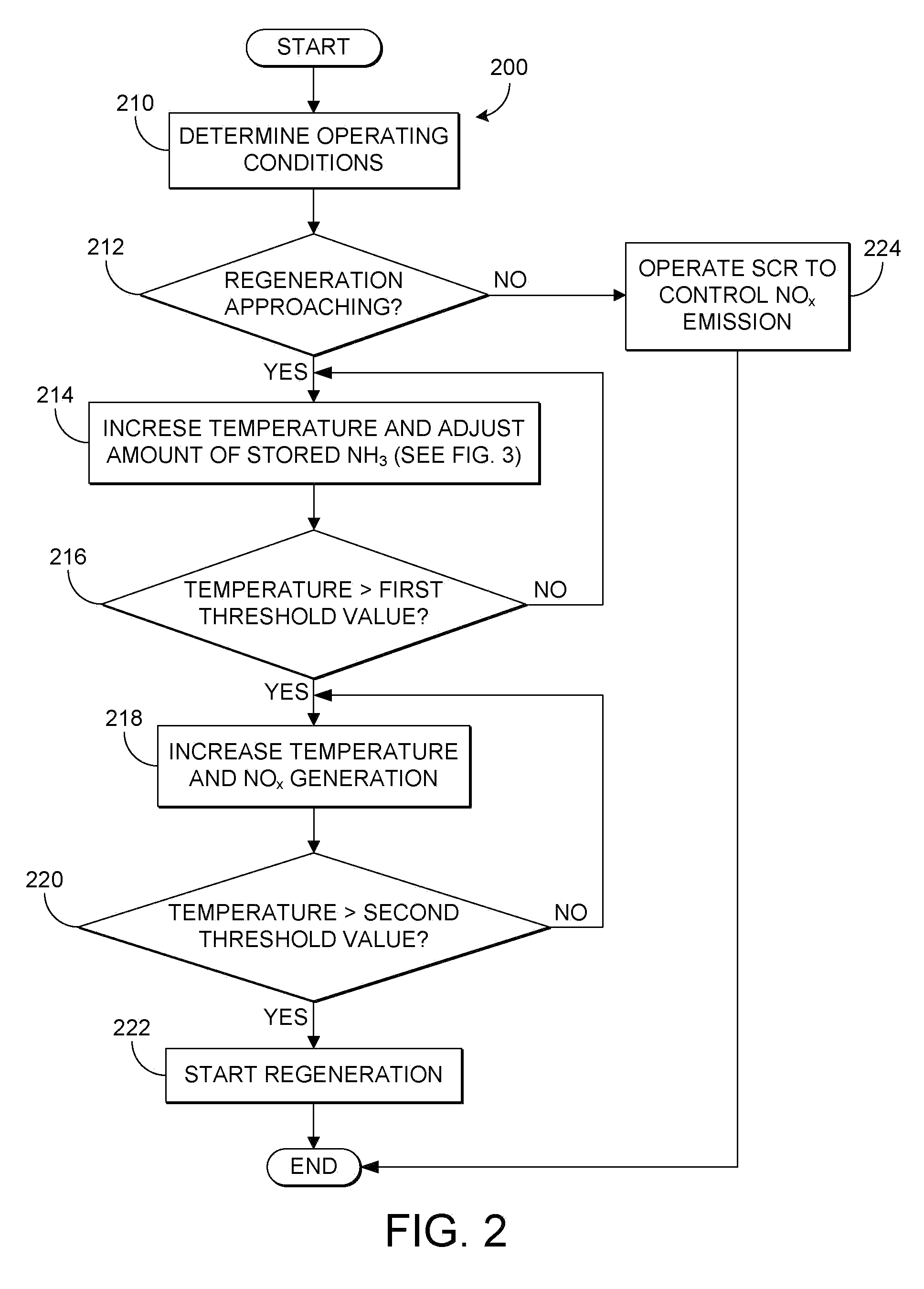
[0013]The following description relates to a method for controlling a diesel aftertreatment system which includes an SCR catalyst and a diesel particulate filter (DPF) coupled to an exhaust system in an engine of a motor vehicle. When an approaching thermal regeneration of the diesel particulate filter is detected, the catalyst enters a first of three phases in which the exhaust temperature is increased while urea injection to the catalyst is decreased and NOx conversion efficiency increases. Upon reaching a first threshold temperature, the catalyst enters a second phase where urea injection is cut-off and NOx emission from the engine is increased in order to quickly consume remaining ammonia that is stored in the catalyst. The temperature is further increased during the second phase in response to a decreasing amount of stored ammonia. During the third phase, once a desired amount of stored ammonia is reached and NOx conversion efficiency begins to decrease, regeneration of the DPF...


PUM


Abstract

Various systems and methods are described for controlling a selective catalytic reduction system coupled to an exhaust system of an engine, the selective catalytic reduction system including a catalyst and a diesel particulate filter. One example method comprises, before regeneration of the diesel particulate filter, adjusting an operating parameter to decrease an amount of ammonia stored in the SCR catalyst to a desired amount of stored ammonia, where the desired amount of ammonia storage is varied based on operating conditions, and initiating regeneration of the catalyst when the desired amount of stored ammonia is reached.

Description


Claims


Application Information

Patent Timeline
Owner FORD GLOBAL TECH LLC
Why Eureka
Try Eureka