

System and method for one-trip hole enlargement operations
a one-trip hole and enlargement technology, applied in the field of drilling operations, can solve the problems of increasing the difficulty of drilling, requiring additional time and expense, reducing the stability of the drilling assembly, and increasing vibrations,
- Summary
- Abstract
- Description
- Claims
- Application Information
AI Technical Summary
Benefits of technology
Problems solved by technology
Method used
Image

Examples
Embodiment Construction
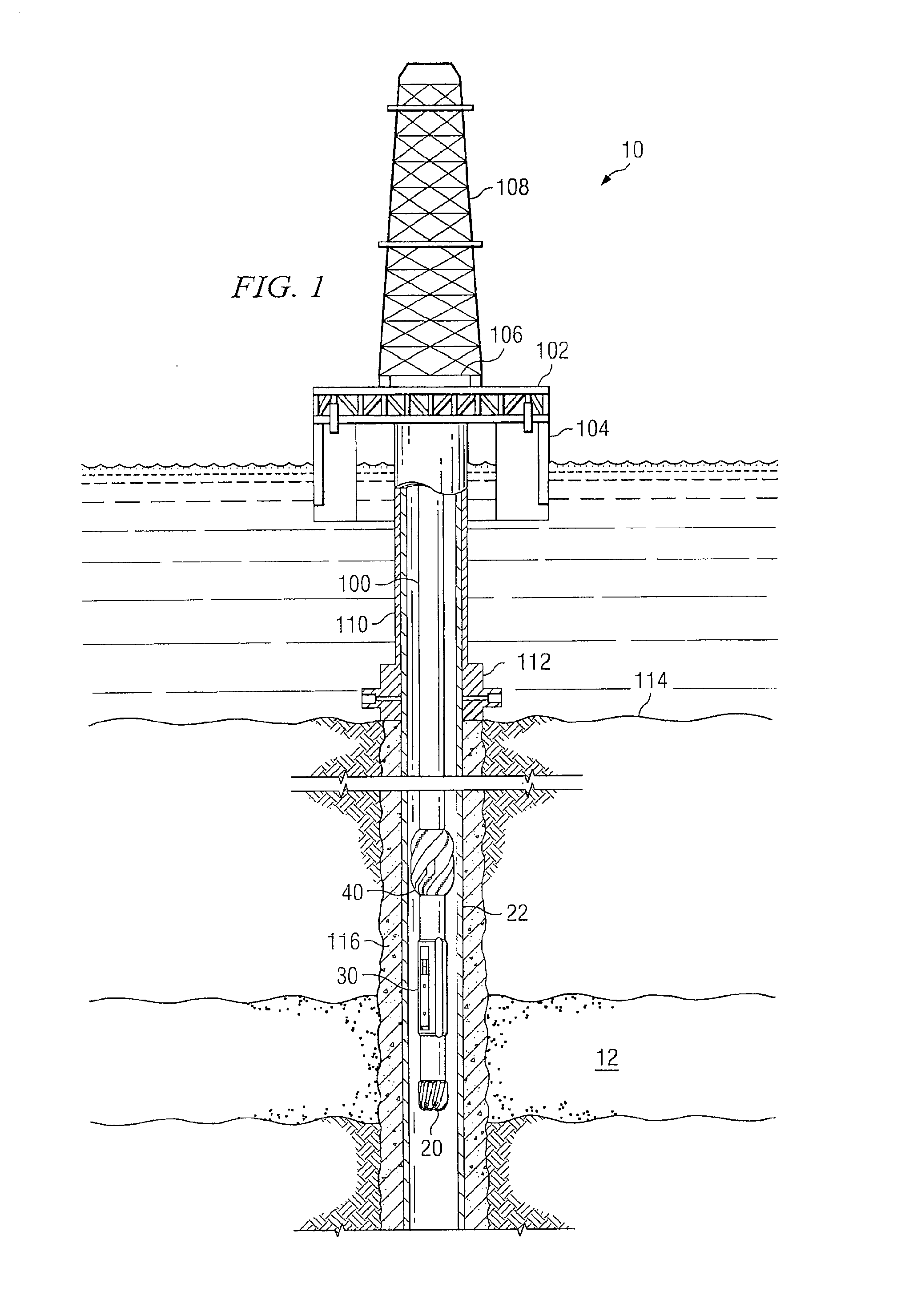
The present disclosure is directed to a system and method for one-trip hole enlargement operations. The teachings of the present disclosure allow more efficient operation of drilling assemblies.
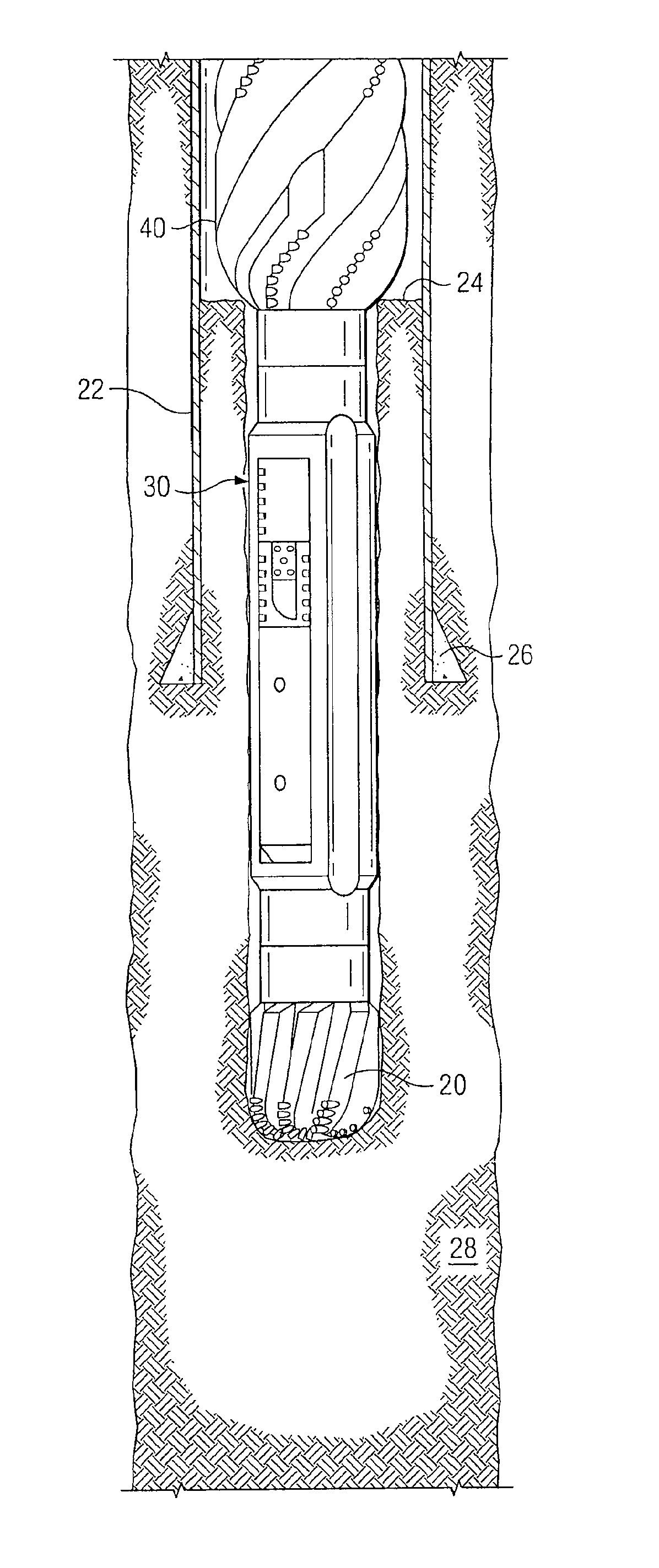
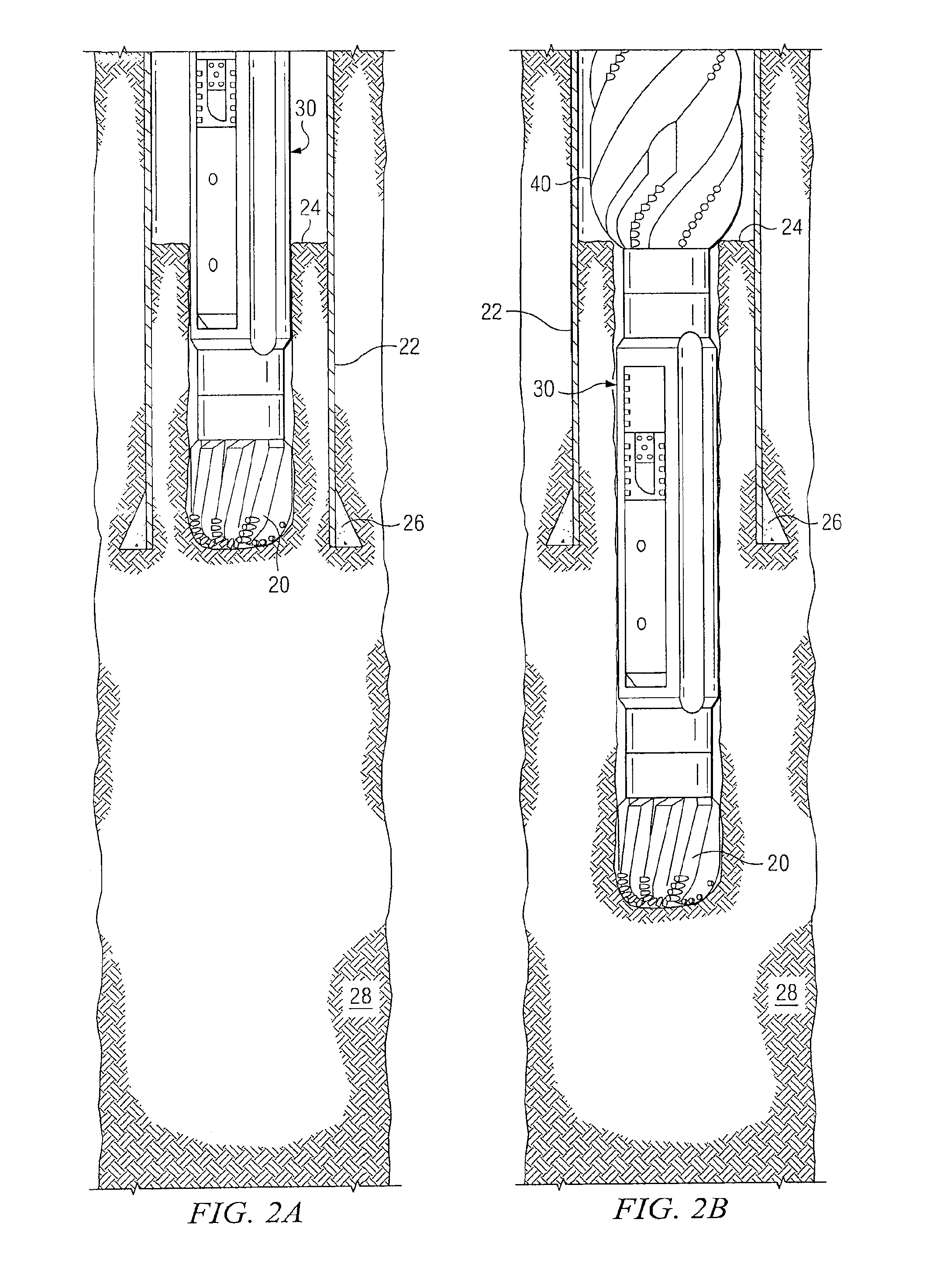
In accordance with a particular embodiment of the present disclosure, a system for simultaneous hole enlargement operations includes a drilling assembly comprising a drill bit. The drilling assembly further comprises an adjustable diameter reamer that is coupled with the drill bit and positioned uphole from the drill bit. The reamer is adjustable between a first diameter and a second diameter that is greater than the first diameter. The drilling assembly further comprises a hole opener that is coupled with and positioned uphole from the reamer. More specifically, the present invention may also includes a stabilizer positioned uphole from the hole opener.
In accordance with another aspect of the present invention, a method is provided, comprising drilling a borehole through material in a casing...
PUM
 Abstract
Description
Claims
Application Information