Radiographic imaging apparatus and radiographic imaging system, control method therefor, and program therefor

a radiographic imaging and imaging apparatus technology, applied in the direction of instruments, radiation controlled devices, optical radiation measurement, etc., can solve the problems of increasing the complexity of the overall apparatus, the risk of reducing image quality, and the management of parameters or correction processing. achieve the effect of reducing the occurrence of an image step and avoiding significant reduction in image quality

Inactive Publication Date: 2011-02-03
CANON KK
View PDF8 Cites 10 Cited by
  • Summary
  • Abstract
  • Description
  • Claims
  • Application Information

AI Technical Summary

Benefits of technology

[0011]As a result of intensive studies to provide an imaging apparatus and system capable of reducing the occurrence of an image step affected by a radiation area, which can occur in an obtained image, and avoiding significant reduction in image quality without performing complex image processing, the inventor of the claimed invention has achieved the following aspects of the invention.

Problems solved by technology

Thus, a ghost (image step), which is affected by the radiation area, occurs in an obtained image, leading to the risk of reduced image quality.
In the correction technique of PTL 2, however, since the correction is performed using image processing, the management of parameters or correction processing is complicated and the complexity of the overall apparatus increases.
In addition, complex operations such as acquiring data in advance for correction are required, and also strict management such as thoroughgoing data sampling is required to obtain stable image quality.
Further, the number of afterimages included in an image signal obtained from the FPD, which may cause the ghosts described above, is not reduced, and therefore it is difficult to obtain optimum effects in various situations.

Method used


Image

  • Radiographic imaging apparatus and radiographic imaging system, control method therefor, and program therefor
  • Radiographic imaging apparatus and radiographic imaging system, control method therefor, and program therefor
  • Radiographic imaging apparatus and radiographic imaging system, control method therefor, and program therefor

Examples


Embodiment Construction

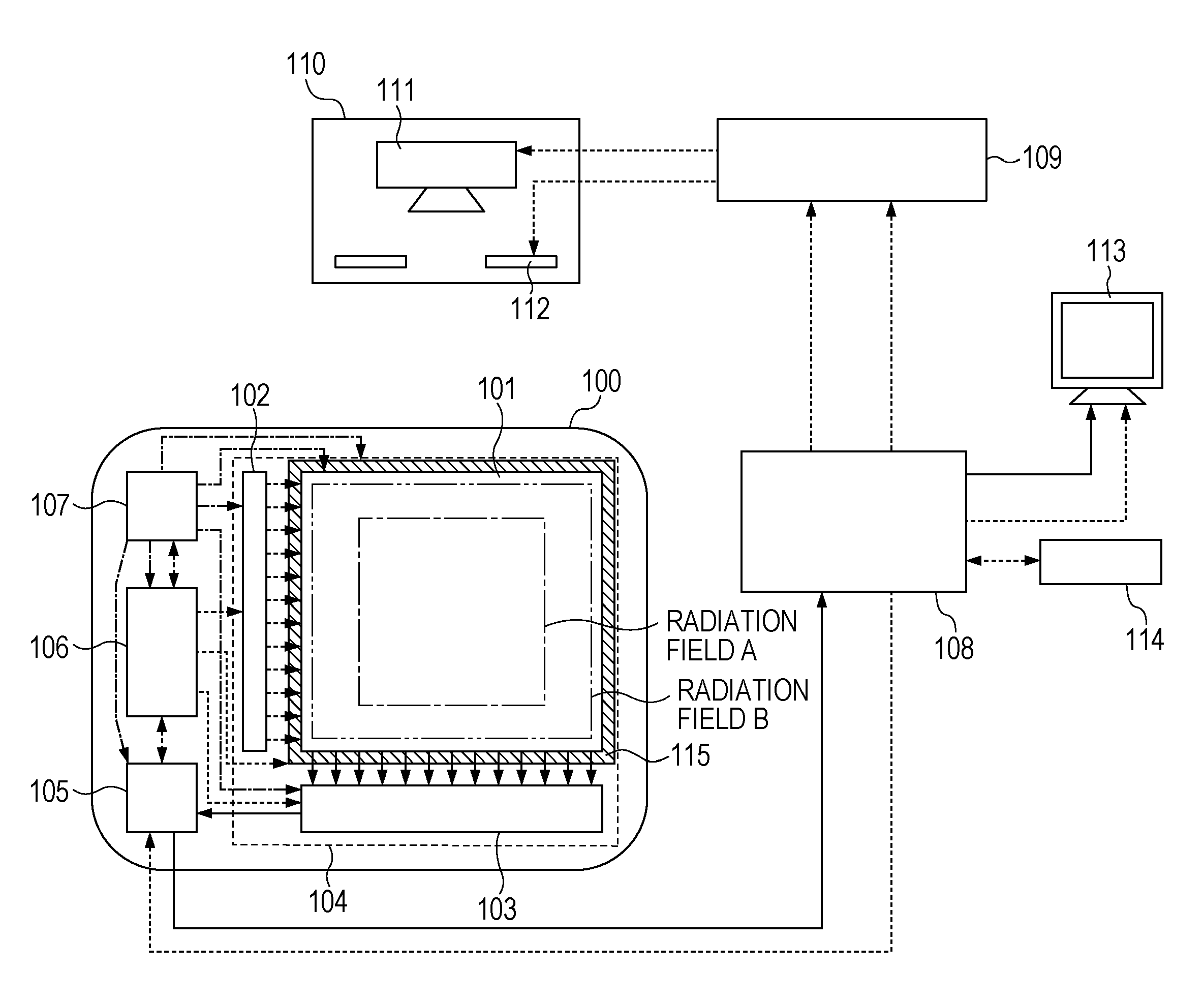
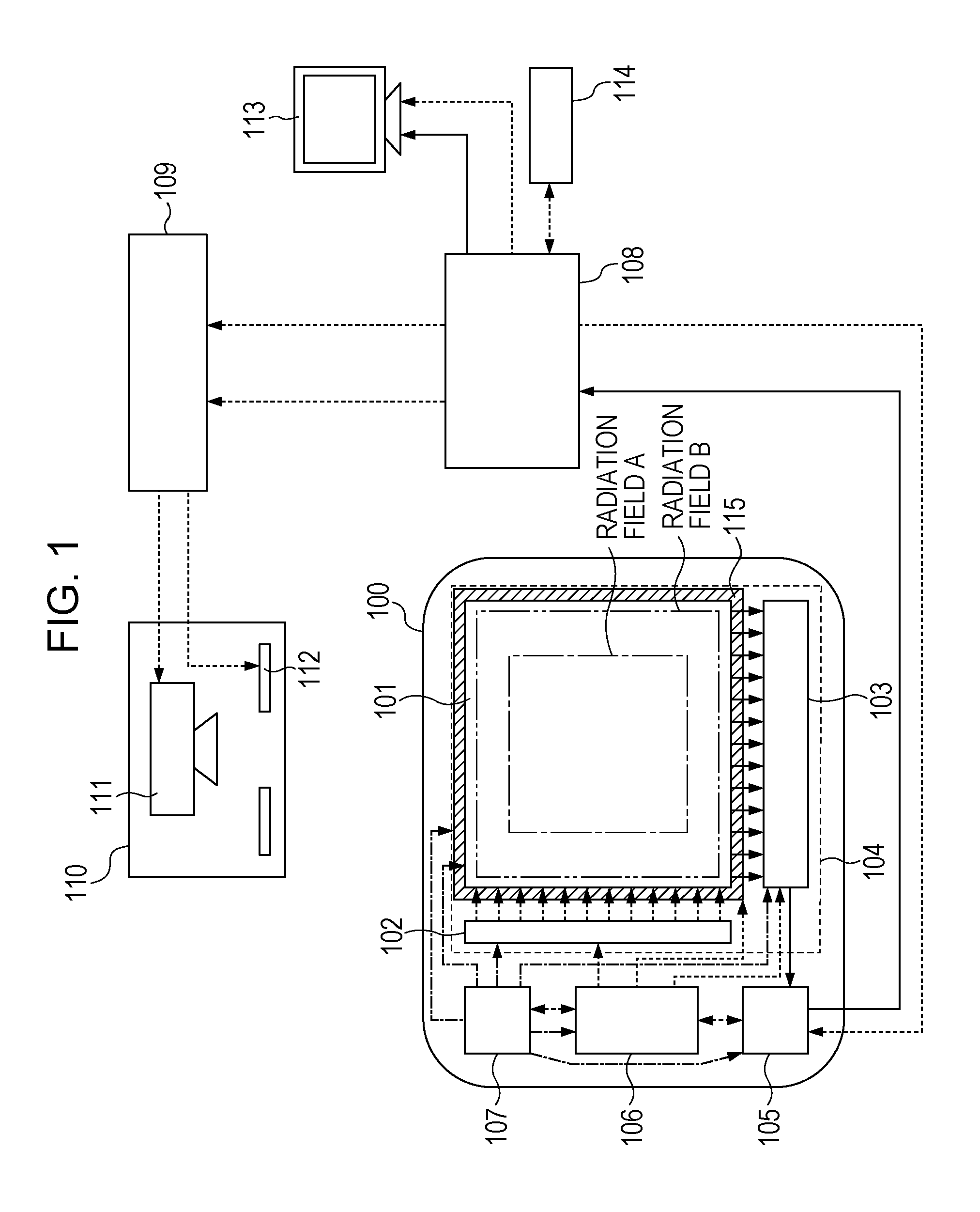
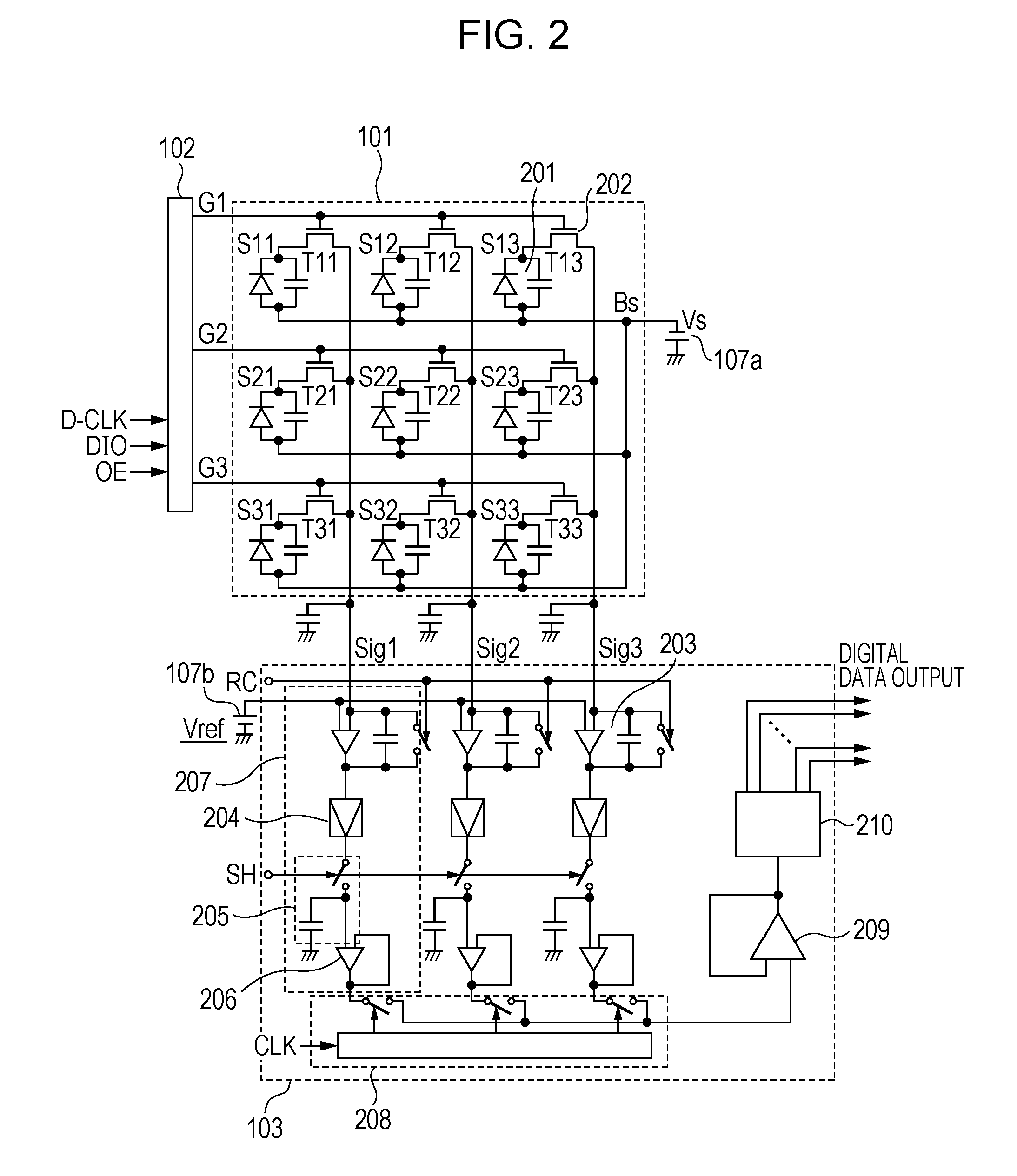
[0034]An embodiment to which the present invention is suitably applicable will be described in detail hereinafter with reference to the drawings. A radiographic imaging system of the present embodiment illustrated in FIG. 1 includes an imaging apparatus 100, a control computer 108, a radiation control device 109, a radiation generating device 110, a display device 113, and a console 114. The imaging apparatus 100 includes a FPD (flat panel detector) 104 including a detection unit 101 having a plurality of pixels that convert radiation or light into electrical signals, a drive circuit 102 that drives the detection unit 101, and a read circuit 103 that outputs the electrical signals from the driven detection unit 101 as image data. The imaging apparatus 100 further includes a signal processing unit 105 that processes the image data from the FPD 104 and that outputs a result, and a control unit 106 that supplies a control signal to each constituent element and that controls the operati...


PUM


Abstract

An imaging apparatus includes a detector, having a plurality of pixels arranged in a matrix, for performing first and second radiography operations, a bias light source, and a control unit that controls the operation of the detector and the bias light source. In the first radiography operation, image data corresponding to radiation in a first radiation field corresponding to some of the pixels is output. In the second radiography operation, image data corresponding to radiation in a second radiation field larger than the first radiation field is output. In accordance with a change from the first radiation field to the second radiation field, the operation of the bias light source is controlled so that the irradiation with the bias light is performed during a period between the first and second radiography operations at a bias-light integral dose determined based on radiation integral dose information in the first radiography operation.

Description

CROSS-REFERENCE TO RELATED APPLICATIONS[0001]This application is a Continuation of International Application No. PCT / JP2009 / 061610, filed Jun. 25, 2009, which is hereby incorporated by reference herein in its entirety.BACKGROUND OF THE INVENTION[0002]1. Technical Field[0003]The present invention relates to an imaging apparatus, a radiographic imaging apparatus, and a radiographic imaging system. More specifically, the present invention relates to an imaging apparatus used in a radiographic imaging apparatus and a radiographic imaging system, which is suitable for use in still image radiography such as general radiography or moving image radiography such as fluoroscopic radiography in medical diagnosis. Note that, in the present invention, the term radiation includes, in addition to α rays, β rays, γ rays, which are beams of particles (including photons) emitted by radiation decay, beams having energy higher than or equal to that of the above rays, for example, X-rays, particle beams...

Claims


Application Information

Patent Timeline
Patent Type & Authority Applications(United States)
IPC IPC(8): H01L27/00G01T1/26
CPCA61B6/06A61B6/4233H04N5/32A61B6/542A61B6/585A61B6/5241
Inventor YOKOYAMA, KEIGOENDO, TADAOKAMESHIMA, TOSHIOAKIYAMA, MASAYOSHIYAGI, TOMOYUKITAKENAKA, KATSUROSATO, SHO
Owner CANON KK
Why Eureka
Try Eureka